Options Adjustments
Item |
|
| Adjustments |
|
|
|
| |
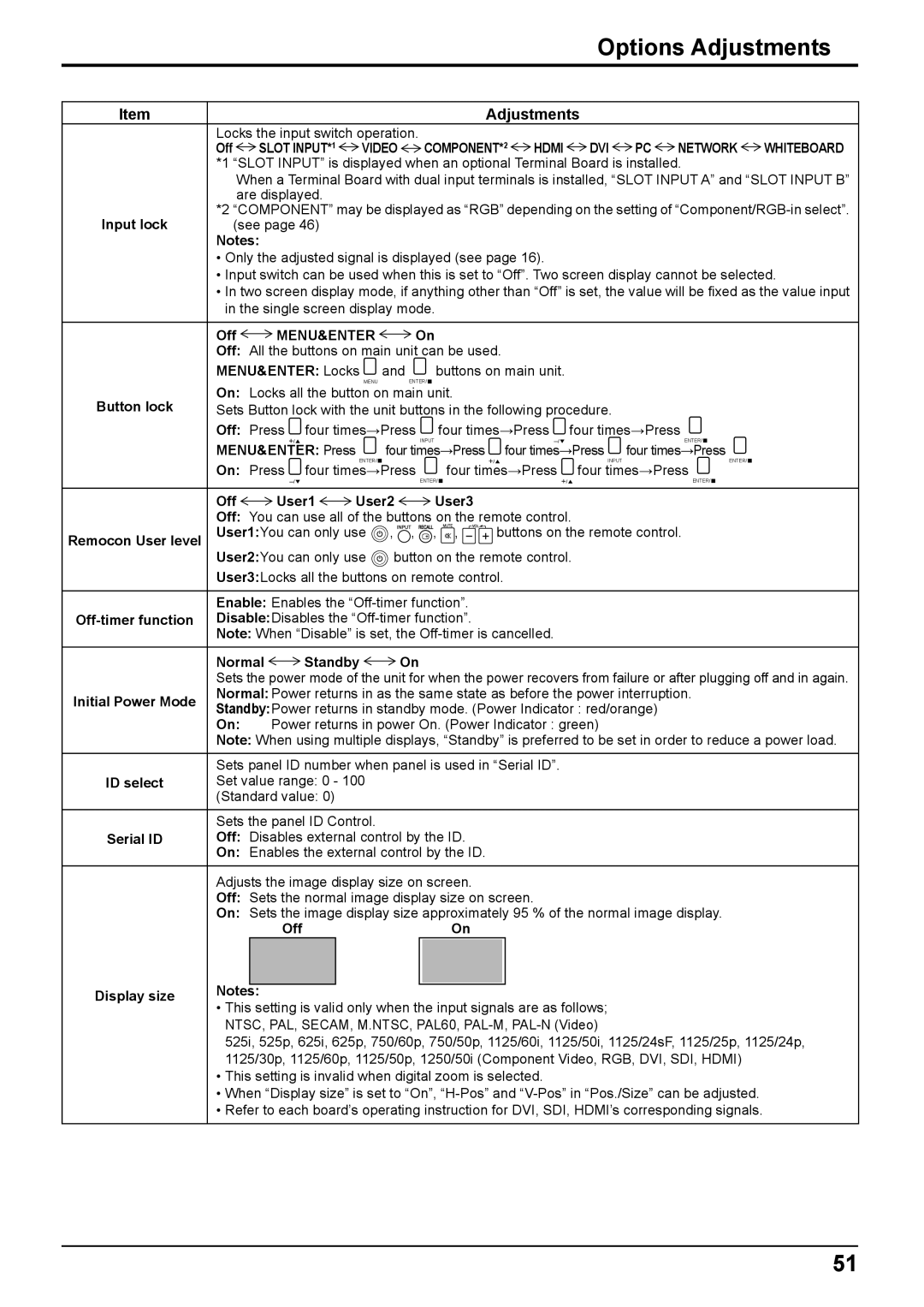
Locks the input switch operation. | COMPONENT*2 | HDMI | DVI | PC | NETWORK | WHITEBOARD | ||
Off SLOT INPUT*1 | VIDEO | |||||||
*1 | “SLOT INPUT” is displayed when an optional Terminal Board is installed. |
| ||||||
| When a Terminal Board with dual input terminals is installed, “SLOT INPUT A” and “SLOT INPUT B” | |||||||
*2 | are displayed. |
|
|
|
|
|
|
|
“COMPONENT” may be displayed as “RGB” depending on the setting of | ||||||||
Input lock | (see page 46) |
|
|
|
|
|
|
|
Notes: |
|
|
|
|
|
|
| |
•Only the adjusted signal is displayed (see page 16).
•Input switch can be used when this is set to “Off”. Two screen display cannot be selected.
•In two screen display mode, if anything other than “Off” is set, the value will be fixed as the value input in the single screen display mode.
Off  MENU&ENTER
  On
On
Off: All the buttons on main unit can be used.
MENU&ENTER: Locks ![]() and
and ![]() buttons on main unit.
buttons on main unit.
MENUENTER/ ![]()
On: Locks all the button on main unit.
Button lock | Sets Button lock with the unit buttons in the following procedure. |
| ||||||||
| Off: Press | four times→Press |
| four times→Press | four times→Press | |||||
| MENU&ENTER: Press |
|
| INPUT |
| four times→Press | ENTER/ | |||
|
| four times→Press | four times→Press | |||||||
| On: Press |
| ENTER/ |
|
| four times→Press | INPUT | ENTER/ | ||
| four times→Press |
| four times→Press | |||||||
|
|
|
|
|
| ENTER/ |
|
|
| ENTER/ |
| Off | User1 | User2 | User3 |
|
|
| |||
| Off: You can use all of the buttons on the remote control. |
| ||||||||
Remocon User level | User1:You can only use | , , | , | , | buttons on the remote control. | |||||
User2:You can only use ![]() button on the remote control.
button on the remote control.
User3:Locks all the buttons on remote control.
| Enable: Enables the | |||||||||
Disable:Disables the | ||||||||||
| Note: When “Disable” is set, the | |||||||||
| Normal | Standby | On | |||||||
| Sets the power mode of the unit for when the power recovers from failure or after plugging off and in again. | |||||||||
Initial Power Mode | Normal: Power returns in as the same state as before the power interruption. | |||||||||
Standby:Power returns in standby mode. (Power Indicator : red/orange) | ||||||||||
| ||||||||||
| On: | Power returns in power On. (Power Indicator : green) | ||||||||
| Note: When using multiple displays, “Standby” is preferred to be set in order to reduce a power load. | |||||||||
| Sets panel ID number when panel is used in “Serial ID”. | |||||||||
ID select | Set value range: 0 - 100 |
|
|
|
|
| ||||
| (Standard value: 0) |
|
|
|
|
| ||||
| Sets the panel ID Control. |
|
|
|
|
| ||||
Serial ID | Off: Disables external control by the ID. | |||||||||
| On: Enables the external control by the ID. | |||||||||
| Adjusts the image display size on screen. | |||||||||
| Off: Sets the normal image display size on screen. | |||||||||
| On: Sets the image display size approximately 95 % of the normal image display. | |||||||||
|
|
| Off |
|
| On | ||||
Display size | Notes: |
|
|
|
|
|
|
|
| |
|
|
|
|
|
|
|
| |||
• This setting is valid only when the input signals are as follows; | ||||||||||
| ||||||||||
| NTSC, PAL, SECAM, M.NTSC, PAL60, | |||||||||
| 525i, 525p, 625i, 625p, 750/60p, 750/50p, 1125/60i, 1125/50i, 1125/24sF, 1125/25p, 1125/24p, | |||||||||
| 1125/30p, 1125/60p, 1125/50p, 1250/50i (Component Video, RGB, DVI, SDI, HDMI) | |||||||||
| • This setting is invalid when digital zoom is selected. | |||||||||
| • When “Display size” is set to “On”, | |||||||||
| • Refer to each board’s operating instruction for DVI, SDI, HDMI’s corresponding signals. | |||||||||
51