Contents
WV-NW474SE
Risk of Electric Shock Do not Open
Contents
Features
Preface
System Requirements
Trademarks
Document Convention
Precautions
Handle the camera with care
Never face the camera towards the sun
Do not aim the camera at the same object for a long time
Major Operating Controls & Their Functions
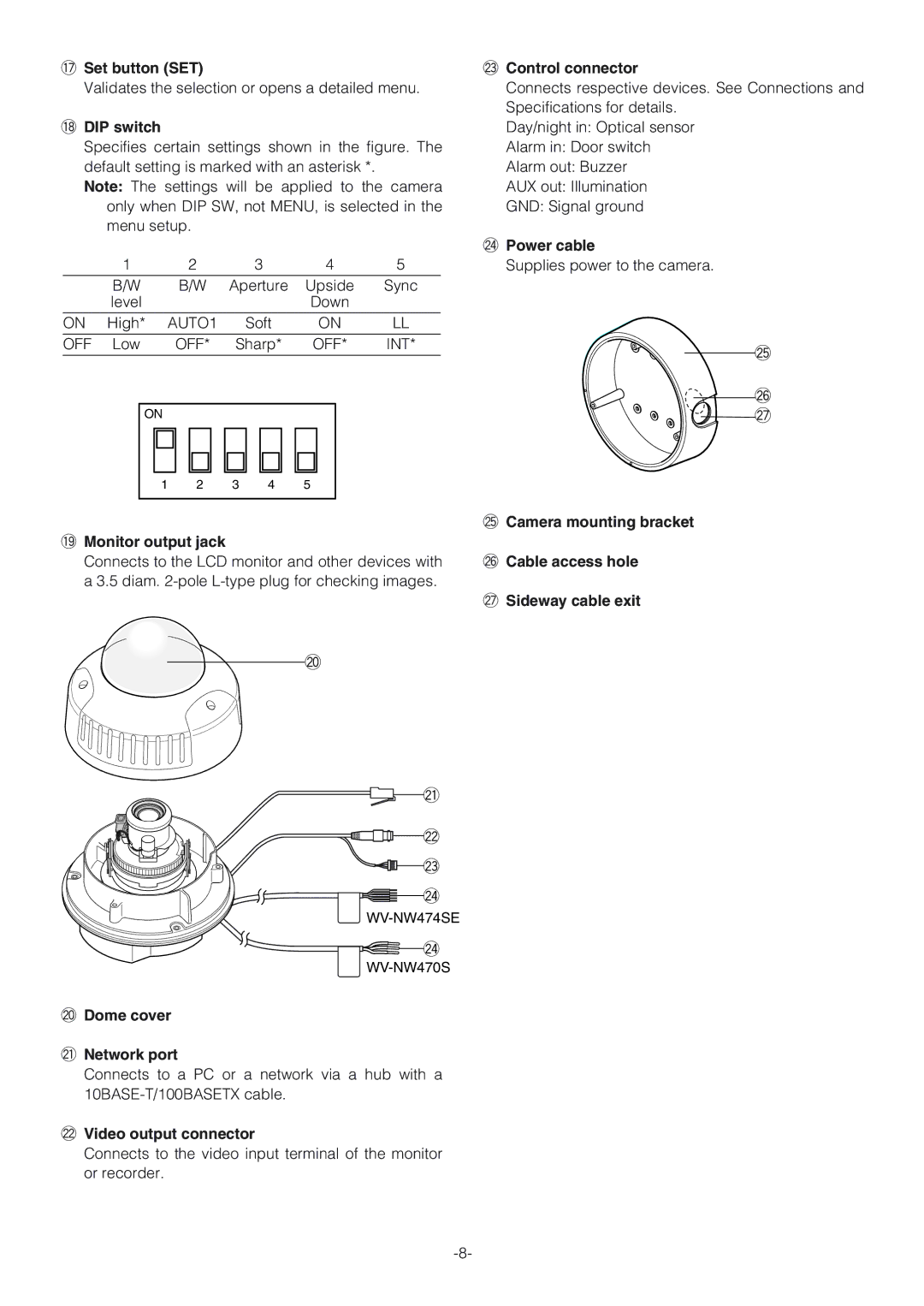
8DIP switch
@3Control connector
@4Power cable
@2Video output connector
Installation
Installation Plans & Preparations
Installation space
Procurement
Mounting the Camera
Optional Heater Unit
Power Connection
Wire colours & functions AC Type
Cable length and wire gauge 24 V AC Type
Connections
Image Adjustment
Control Connector
Video Output Connection
Network Port Connection
Waterproof Process
Network Connection Types
Direct Connection to PC Type
Connection to Intranet Type
Connection to Internet Type
Network Setup of Your PC
Preparations for Network Connections
Network Setup of the Camera
Using Panasonic IP Setup Software
Dhcp DNS
Ddns
Page
Prior to Camera Setup
Buttons Used for Setup
Camera Setup Menus
ALL Reset button
¡From the Camera
Setup Menu Tree
Setting Procedures
Setup Selection
Camera Setup Menu CAM
Camera Identification Camera ID Setting
Light Control Setting ALC
Command Usage
To edit the Camera ID
To replace a specific character in the Camera ID
Electronic Sensitivity Enhancement Sens UP
Gain Control Setting AGC on DNR-L, DNR-H/OFF
Shutter Speed Setting Shutter
ATW1 Auto-Tracing White Balance
Synchronization Setting Sync
White Balance Setting White BAL
Motion Detector Setting Motion DET
Automatic White Balance Control Mode AWC
Manual Fine Adjustment for AWC ATW
Push SW
Menu/DIP SW Selection
Special Menu Special
To reset to the factory settings Camera Reset
10-6. BW
Network Setup Network Setup
Http Port Number
Initializing the Setup Menu
Initializing
Initializing the Camera Menu
Initializing Html Files
Troubleshooting
Specifications
TCP/IP, HTTP, FTP, SMTP, DNS, DDNS, DHCP, ARP, BOOTP, NTP
Prevention of Blooming and Smear
Network Section
Standard Accessories
Optional Accessories
General
WV-NW474SE
Appendix
Optional Heater Unit WV-CW3HE
在日本印刷

 @7
@7