Customizing V.35-Compatible Units
Displaying Switchpack Definitions
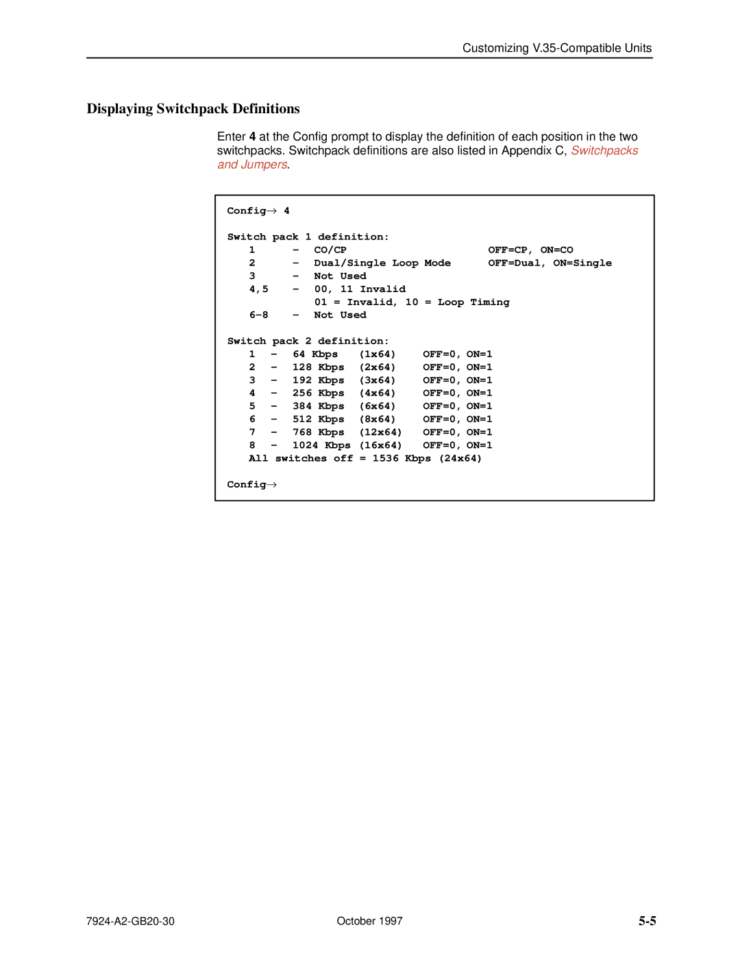
Enter 4 at the Config prompt to display the definition of each position in the two switchpacks. Switchpack definitions are also listed in Appendix C, Switchpacks and Jumpers.
Config→ | 4 |
|
|
|
| |
Switch pack 1 definition: |
|
| ||||
1 |
| ± | CO/CP |
|
| OFF=CP, ON=CO |
2 |
| ± | Dual/Single Loop Mode | OFF=Dual, ON=Single | ||
3 |
| ± | Not Used |
|
| |
4,5 |
| ± | 00, 11 Invalid |
|
| |
|
|
| 01 = Invalid, 10 = Loop Timing | |||
6±8 |
| ± | Not Used |
|
| |
Switch pack 2 definition: |
|
| ||||
1 | ± | 64 Kbps | (1x64) | OFF=0, ON=1 | ||
2 | ± | 128 | Kbps | (2x64) | OFF=0, ON=1 | |
3 | ± | 192 | Kbps | (3x64) | OFF=0, ON=1 | |
4 | ± | 256 | Kbps | (4x64) | OFF=0, ON=1 | |
5 | ± | 384 | Kbps | (6x64) | OFF=0, ON=1 | |
6 | ± | 512 | Kbps | (8x64) | OFF=0, ON=1 | |
7 | ± | 768 | Kbps | (12x64) | OFF=0, ON=1 | |
8 | ± | 1024 Kbps | (16x64) | OFF=0, ON=1 | ||
All switches off = 1536 Kbps (24x64)
Config→
October 1997 |
