Switchpacks and Jumpers
Switchpack S1
VT100 Terminal
Modular Jack
|
|
|
|
| 8 |
|
|
|
|
|
|
| |
|
|
|
|
|
|
|
|
|
|
|
|
|
|
|
|
|
|
| 7 |
|
|
|
|
|
| 6 |
|
|
|
|
|
|
| |
|
|
|
|
| 5 |
|
|
|
|
|
|
| |
|
|
|
|
|
| |
|
|
|
|
| 4 |
|
|
|
|
|
|
| |
|
|
|
|
|
| |
|
|
|
|
|
|
|
|
|
|
|
| 3 |
|
|
|
|
|
|
|
|
|
|
|
|
|
| |
|
|
|
|
| 2 |
|
|
| ON |
|
| 1 |
|
|
|
|
|
| ||
|
|
|
|
|
| |
|
|
|
|
|
|
|
|
|
|
|
|
|
|
Position | Settings* | |||||
|
|
|
|
|
|
|
1 | OFF = CP | |||||
| ON = CO | |||||
|
|
|
|
|
|
|
2 | OFF = AMI line | |||||
|
|
|
| encoding | ||
| ON = B8ZS line | |||||
|
|
|
| encoding | ||
|
|
|
|
|
|
|
3 | OFF = Loops A and B | |||||
| ON = Loop A | |||||
|
|
|
|
|
|
|
4, 5, 6 | 000 = | |||||
| 100 = | |||||
| 010 = | |||||
| 110 = | |||||
| 001 = | |||||
|
|
|
|
|
|
|
7, 8 | 00 = Unframed | |||||
| 01 = D4 | |||||
| 11 = ESF | |||||
|
|
|
|
|
|
|
P1 | P10 |
|
1 2 3 | 1 2 3 |
|
| P3 |
|
| S1 |
|
| 1 2 |
|
| 1 2 3 | P11 |
| 1 2 3 |
|
| P8 |
|
| P12 |
|
| 1 2 3 |
|
| 3 2 1 |
|
| P9 |
|
Jumper P11
Pins* | Settings* |
|
|
Terminal Mode | |
|
|
Switchpack Mode | |
|
|
* Default in bold | HDSL Line Jack |
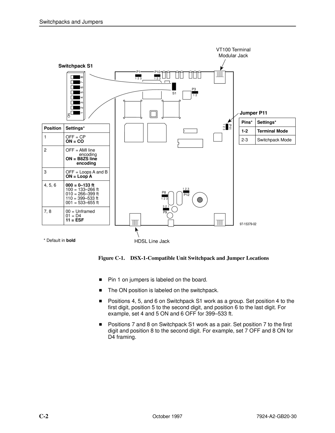
Figure C-1. DSX-1-Compatible Unit Switchpack and Jumper Locations
HPin 1 on jumpers is labeled on the board.
HThe ON position is labeled on the switchpack.
HPositions 4, 5, and 6 on Switchpack S1 work as a group. Set position 4 to the first digit, position 5 to the second digit, and position 6 to the last digit. For example, set 4 and 5 ON and 6 OFF for 399±533 ft.
HPositions 7 and 8 on Switchpack S1 work as a pair. Set position 7 to the first digit and position 8 to the second digit. For example, set 7 OFF and 8 ON for D4 framing.
October 1997 |