Acculink DSU/CSU
Copyright 2001 Paradyne Corporation All rights reserved
Important Safety Instructions
United States EMI Notice
316x DSU/CSU Facility Interface Codes Description
Government Requirements and Equipment Return United States
Canada
Contents
Configuration
Using the Front Panel
March
Security
Using the Integral Modem
Testing
Monitoring and Troubleshooting
Configuration Options
Front Panel Menu Technical SpecificationsT
ConfigurationTWorksheets
Pin Assignments
IP Network Addressing Scenarios
Snmp MIB Objects
Asynchronous Terminal Interface Operation
Front Panel Emulation
Equipment List Glossary Index
Viii
Document Purpose and Intended Audience
About This Guide
Document Summary
Document Number Document Title
Product-Related Documents
Reference Documents
Xii
Introduction
Features
Overview
Telnet Access
Alarm Message Capability
DTE Drop/Insert DSX-1 Interface
Front Panel Emulation
Snmp Management Support
Physical Description
Standalone DSU/CSU Front Panel
Acculink
DSU/CSU Rear Panel
Standalone DSU/CSU Rear Panel
Power Port COM Modem
Power
Standalone DSU/CSU Rear Panel Connectors Name Function
Introduction March
Application Examples
Installation
Network
Direct Connection
Snmp or Telnet Connection Examples
Representative
Important Instructions
Procedure
Installation Steps
Installing the +24 Vdc Power Supply
Optional Power Sources Model 3164 Only
48 Vdc Single Source Power Supply Pinouts
Installing the Single -48 Vdc Power Supply
10. -48 Vdc Redundant Source Power Supply Pinouts
Installing the Redundant -48 Vdc Power Supply
11. Cabling Examples
Cabling Examples
Power-On Self-Test
Top-level menu screen appears
Installation March
Front Panel
Using the Front Panel
LCD
Keypad
Keypad
Test Jacks Standalone DSU/CSU
Test Jacks
DSU/CSU LEDs
LEDs
Fail
System LEDs Name Color Meaning
Name Color Meaning
Network Interface LEDs
PDV
DTE Drop/Insert DSX-1 Interface LEDs Name Color Meaning
DTR
Data Port LEDs Name Color Meaning
Displaying Unit Identity
Ser=xxxxxxx
Selecting the DTE Drop/Insert or Data Port for LED Display
Displaying LED Conditions
Use the and keys to scroll LED names onto the screen
Download Operations
Resetting the DSU/CSU
Using the Front Panel March
Configuration
Setting Customer Identification
Changing Configuration Options
Configuration
Displaying/Editing Configuration Options
Saving Edit Changes
Selecting/Copying to a Specific Port
Copy From Prt1 Prt2 Prt3
Configuring the 10BaseT Port Models 3160
Setting the 10BaseT Port IP Address
Setting the 10BaseT Port Subnet Mask
Setting the Default Gateway Address
Appendix C, Configuration Options
Selecting the Port
Setting the IP Address
Com IP Adr Next Edit Clear
Selecting the Link Layer Protocol
Com Link Next PPP Slip
Specifying the Community Names and Access Types
Public Down Save
Enabling Snmp Trap Messages
Configuring Snmp Traps
Selecting the Number of Trap Managers
Configuring a Destination for Snmp Traps
Configuring DS0 Channels
Example of Channel Allocation
Example of Interface Worksheet for Network Interface
Network Interface Network Channel Allocation
Example of Interface Worksheet for DTE Drop/Insert Interface
Example of RBS Information Worksheet
DTE Chan Config Assign N1 Voice RBS or Data
Port Chan Conf Options Value
Port Channel Configuration Worksheet Ports 1
Port Channel Configuration Worksheet Ports 3
Displaying DS0 Channel Assignments
Display Channel Symbols Meaning
From the Channel Config screen, select Dsply
Acami
Allocating Data Ports
EditDTE Port NET Chan
Block or Acami Assignment Method
Individual Channel Assignment Method
From the Channel Config screen, select DTE
From the DTE Channels screen, press F1 to select Assign
Clearing DS0 Channel Allocation
Selecting the Timing Source
Providing Backup Capability
Common Clocking Configurations
Configuring for Network Timing
Configuring for External Timing
Enabling the COM Port for Carrier-Mounted DSU/CSUs
Configuration
Ascii HEX
Control Sequence
Command Complete screen appears
Deactivating the Alarm Relay for Carrier-Mounted DSU/CSUs
Configuration March
Security
Establishing Access Security on a Port
Setting a Password
Entering a Password to Gain Access
Acquiring the Active User Interface
Acquiring/Releasing the User Interface
Releasing the Active User Interface
Enabling/Disabling the Front Panel
Security March
User Interface Access Security for Standalone DSU/CSUs
Changing User Interface Access Security
Using the Integral Modem in Standalone DSU/CSUs
Using the Integral Modem
Entering Numbers in the Phone Directories
Xxxxxxxxxxxxxxxxx Up Down Save
Valid Phone Number Characters Meaning Restrictions
Initiating a Call for Front Panel Pass-Through Operation
From the Call Setup screen, select Pass
Dial n
Disconnecting the Modem Connection
Procedure
Monitoring and Troubleshooting
Self-Test Health Messages
Self-Test Health Messages Description
Device Health and Status Messages
Device Health and Status Messages 1 Description
Device Health and Status Messages 2 Description
Performance Reports
Select User registers
User Intvl Up Down Dsply
Control Rel LED ClrReg
Event
CurTimer
VldIntvl
Complete
StEvnt
Ethernet Statistics Models 3160
Ethernet Statistics Symbol Description
Frames transmitted
Frames received
Yellow Alarm signal received at the x Interface
Alarms
Snmp Traps
Snmp Trap per Interface Trap Meaning
Enterprise-Specific Trap Definitions Trap Value Event
Troubleshooting 1 Symptom Possible Cause Solutions
Troubleshooting
OOF at DTE
Troubleshooting 2 Symptom Possible Cause Solutions
Network
Troubleshooting 3 Symptom Possible Cause Solutions
Testing
Net
Test Jacks
Mon
Eqp
NET Out
Test Jack Functions Test Jack Name
Eqpt
Eqpt Out
Test Jack Configuration Model 3160 and 3164 DSU/CSUs
Remote Loopback Tests
Test Commands
For Networks
For Channels
DSU/CSU
Sending a Line Loopback Up or Down
Sending a V.54/ANSI FT1 Activation/Deactivation
Valid Loopback Combinations
Local Loopback Tests
Line Loopback LLB
Payload Loopback PLB
DTE Loopback DLB
Repeater Loopback RLB
Data Channel Loopback Dclb
Data Terminal Loopback Dtlb
Aborting Loopbacks
Test Patterns
Sending Test Patterns
In8 511 Network Port
Valid Send Test Pattern Combinations
Network Qrss Port
Network Port
Monitoring Test Patterns
Aborting Test Patterns
Starting a Lamp Test
Lamp Test
Aborting a Lamp Test
Test Status Message Description
Displaying DSU/CSU Test Status
Testing March
DSU ESF
Front Panel Menu
Front Panel Menu March
Power Requirements
Technical Specifications
10BaseT Interface
Models 3160/3164
Configuration Options
Table C-1. DTE Interface Configuration Options 1
DTE Interface Configuration Options
Table C-1. DTE Interface Configuration Options 2
Port Configuration Options
Table C-2. Port Configuration Options 1
All Ones Both Next Disab DTR RTS Both Prev
Table C-2. Port Configuration Options 2
Rcv Yellow Halt Next None Halt Prev
Table C-2. Port Configuration Options 3
Tx Clock Int Next Int Ext Prev
InvertTxC Auto Next Auto Enab Disab Prev
EDL Disab Next Enab Disab Prev
Table C-2. Port Configuration Options 4
Near-end Disab Next Disab Maint Send Both Prev
Table C-2. Port Configuration Options 5
Far-end Disab Next Disab Maint Prev
Mgmt Link Disab Next Enab Disab Prev
Table C-3. Network Interface Configuration Options 1
Network Interface Configuration Options
NET LLB Enab Next Enab Disab Prev
Table C-3. Network Interface Configuration Options 2
NET PLB Enab Next Enab Disab Prev
Bit Stuff Next 62411 Part68 Disab Prev
Table C-3. Network Interface Configuration Options 3
Channel Configuration Options
Circuit Ident Next Edit Clear Prev
DTE Channels Assign Voice
Table C-4. DTE Channel Configuration Options
N10 N11 N12 N13 N14 N15 N24
Value Meaning
Channel Config Dsply Clear DTE Prt1 Prt2 Prt3 Prt4
Table C-5. Data Port Channel Configuration Options 1
Assign To NET Next NET DTE Prtn Prtn Prtn Prev
Assign By Block Next Block Acami Chan Prev
Table C-5. Data Port Channel Configuration Options 2
Table C-5. Data Port Channel Configuration Options 3
N10 N11 N12 N24 Next Prev D10 D11 D12 D24
Table C-5. Data Port Channel Configuration Options 4
Table C-6. General Configuration Options 1
General Configuration Options
Gen Yellow Enab Next Enab Disab Prev
Clock Src NET Next NET DTE Prt1 Int Ext Prev
Tst Timeout Enab Next Enab Disab Prev
Table C-6. General Configuration Options 2
Clock Rate Next 2048 1544 8 Prev
Tst Duration Next Up Down Save Prev
Table C-7. User Interface Configuration Options 1
User Interface Configuration Options
Password None Next None Com Modem Both Prev
Table C-7. User Interface Configuration Options 2
Com Port Disab Next Enab Disab Prev
Com Use Ascii Next Mgmt Ascii Daisy Term Prev
ComConnPrefix Next Edit Clear Prev
Table C-7. User Interface Configuration Options 3
ComConnected Next Edit Clear Prev
ComEscapeSeq Next Edit Clear Prev
Table C-7. User Interface Configuration Options 4
ComEscDel None Next None 0.2s 0.4s 0.6s 0.8s 1.0s Prev
ComDisconnect Next Edit Clear Prev
Table C-7. User Interface Configuration Options 5
Com Type Async Next Async Sync Prev
Com Clk Int Next Int Ext Prev
Table C-7. User Interface Configuration Options 6
Table C-7. User Interface Configuration Options 7
Table C-7. User Interface Configuration Options 8
Table C-7. User Interface Configuration Options 9
Table C-7. User Interface Configuration Options 10
TnInActTm Disab Next Enab Disab Prev
Table C-7. User Interface Configuration Options 11
TnDiscTm Next Up Down Save Prev
Table C-8. Alarm Configuration Options 1
Alarm Configuration Options
Alrm Msg Disab Next Disab Modem Com Both Prev
Snmp Trap Disab Next Enab Disab Prev
Dial Delay Next 1 2 3 4 5 6 7 8 9 10 Prev
Table C-8. Alarm Configuration Options 2
DialOut Disab Next Enab Disab Prev
Call Retry Disab Next Enab Disab Prev
Next None 1 2 3 4 5 Prev
Table C-8. Alarm Configuration Options 3
AlrmRelay Disab Next Enab Disab Prev
Table C-8. Alarm Configuration Options 4
Table C-9. General Management Configuration Options 1
Management Configuration Options
Table C-9. General Management Configuration Options 2
Access 1 Read Next Read R/W Prev
Table C-9. General Management Configuration Options 3
Access 2 Read Next Read R/W Prev
CommunityName2 Next Edit Clear Prev
NetMask Next Edit Clear Prev
Table C-9. General Management Configuration Options 4
Com IP Adr Next Edit Clear Prev
Com NetMask Next Edit Clear Prev
Modem IP Adr Next Edit Clear Prev
Table C-9. General Management Configuration Options 5
Mdm NetMask Next Edit Clear Prev
Alt Mdm IP Adr Next Edit Clear Prev
Modem Link PPP Next PPP Slip Prev
Table C-9. General Management Configuration Options 6
Aux IP Adr Next Edit Clear Prev
Aux NetMask Next Edit Clear Prev
Table C-9. General Management Configuration Options 7
Num Trap Mgrs Next 1 2 3 4 5 6 Prev
Table C-10. Management Trap Configuration Options 1
Trapn IP Adr Next Edit Clear Prev
Gen Trap Both Next Disab Warm Auth Both Prev
Table C-10. Management Trap Configuration Options 2
Entp Trap Enab Next Enab Disab Prev
Link Trap Both Next Disab Up Down Both Prev
Trap I/F All Next NET DTE T1s Ports All Prev
Table C-10. Management Trap Configuration Options 3
Configuration Worksheets
Configuration Worksheets
Net Options
DTE Options
General Options
User Options
Alarm Options
Prt2 Options
Prt1 Options
Prt4 Options
Prt3 Options
Network Interface Network Channel Allocation
DTE Drop/Insert DSX-1 Interface DTE DSX-1 Channel Allocation
DTE Chan Config Assign N1 Voice RBS or Data
Port Chan Conf Options
Port Chan Conf Options
General Mgmt Options
Mgmt Trap Options
Configuration Worksheets March
Pin Assignments
Table E-1. T1 Network Interface Connector Signal Pin Number
T1 Network Interface
Figure E-1. T1 Line Interface Cable, RJ48C-to-RJ48C
Figure E-3. DTE Drop/Insert DSX-1 Cable
DTE Drop/Insert Interface
Use Pin #
10BaseT Connector
Modem Port Interface
Table E-3. Modem Port Interface Signal Pin Number
AUX Port Interface Model 3164 Only
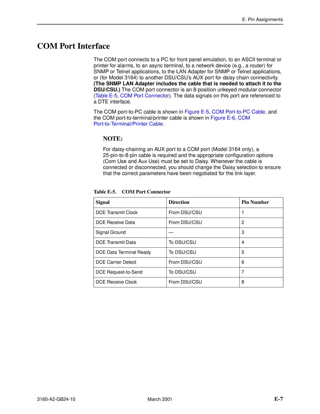
COM Port Interface
Table E-5. COM Port Connector Signal Direction Pin Number
Figure E-5. COM Port-to-PC Cable
Table E-6. EIA-530-A Port Interface Connector Circuit
EIA-530-A Port Interface Connector
Signal Mnemonic Number Direction Pin
Figure E-7. EIA-530-A-to-RS-449 Adapter
EIA-530-A-to-RS-449 Cable Interface
Table E-7. RS-449 Cable Interface Circuit
Figure E-8. EIA-530-A-to-V.35 Adapter
EIA-530-A-to-V.35 Cable Interface
Pin Assignments
EIA-530-A-to-X.21 Cable Interface
Pin
Serial Crossover Cable
Pin P2
Optional DC Power Cable Model 3164 Only
Power Input Connector
Table E-10. DC Power Connector Signal Pin Number
External Clock Interface
Table E-11. External Clock Connector Signal Pin Number
Pin Assignments March
MIB II RFC
Snmp MIB Objects
System Group, MIB
MIB II RFC
System Group sysObjectID Object system
System Group sysServices Object system
System group sysContact Object system
System Group sysName Object system
Interface Group ifNumber Object interfaces
Interface Group, MIB
Interface Group ifIndex Object ifEntry
DTE T1
Interface Group ifType Object ifEntry
Interface Group ifDescr Object ifEntry
Interface Group ifMtu Object ifEntry
Interface Group ifSpeed Object ifEntry
Interface Group ifAdminStatus Object ifEntry
Interface Group ifLastChange Object ifEntry
Interface Group ifOperStatus Object ifEntry
Interface Group Input Counters objects ifEntry 10 to ifEntry
IP Group ipForwarding Object ip
IP Group, MIB
IP Group ipAddrTable Object ip
IP Group ipAdEntAddr Object ipAddrEntry
IP Group ipRouteTable Object ip
IP Group ipRouteIfIndex Object ipRouteEntry
IP Group ipRouteDest Object ipRouteEntry
IP Group ipRouteMetric2 Object ipRouteEntry
IP Group ipRouteProto Object ipRouteEntry
TCP Group, MIB
Icmp Group, MIB
UDP Group, MIB
Transmission Group, MIB
Snmp Group, MIB
DS1/E1 MIB RFC
Near End Group, DS1/E1 MIB
Near End Group dsx1ValidIntervals Object dsx1ConfigEntry
Near End Group dsx1TimeElapsed Object dsx1ConfigEntry
Near End Group dsx1LineType Object dsx1ConfigEntry
Near End Group dsx1LineCoding Object dsx1ConfigEntry
Near End Group dsx1LoopbackConfig Object dsx1ConfigEntry
Near End Group dsx1CircuitIdentifier Object dsx1ConfigEntry
Near End Group dsx1LineStatus Object dsx1ConfigEntry
Near End Group dsx1SignalMode Object dsx1ConfigEntry
Near End Group dsx1Fdl Object dsx1ConfigEntry
Near End Group The DS1 Total Table Objects dsx1TotalEntry
Far End Group, DS1/E1 MIB
DS1 Fractional Group, DS1/E1 MIB
RS-232-like MIB RFC
Number of Ports rs232Number Object rs232
General Port Table rs232PortIndex Object rs232PortEntry
General Port Table, RS-232-like MIB
General Port Table rs232PortInSpeed Object rs232PortEntry
General Port Table rs232PortType Object rs232PortEntry
General Port Table rs232PortOutSpeed Object rs232PortEntry
Asynchronous Port Table, RS-232-like MIB
Input Signal Table rs232InSigName rs232InSigEntry
Input Signal Table, RS-232-like MIB
Input Signal Table rs232InSigState rs232InSigEntry
Input Signal Table rs232InSigChanges rs232InSigEntry
Output Signal Table rs232OutSigName rs232OutSigEntry
Output Signal Table, RS-232-like MIB
Output Signal Table rs232OutSigState rs232OutSigEntry
Output Signal Table rs232OutSigChanges rs232OutSigEntry
Generic Interface Test Table, Generic Interface MIB
Snmp MIB Objects
Enterprise MIB
Correlation between Menu Commands and Snmp Objects
Dsx1CurrentES
Dsx1TimeElapsed
Dsx1CurrentUAS
Dsx1CurrentSES
Set dsx1LoopbackConfig for Net T1 to dsx1NoLoop
Set dsx1LoopbackConfig for Net T1 to dsx1LineLoop
Set dsx1LoopbackConfig for Net T1 to dsx1PayloadLoop
Set dsx1LoopbackConfig for DTE T1 to dsx1LineLoop
Set/Display dsx1FracNumber and dsx1Fracifindex for DTE or
Set/Display dsx1FracNumber and dsx1FracIfindex for DTE T1
Display rs232PortInSpeed or rs232PortOutSpeed for port n
Set/Display rs232PortInSpeed or rs232PortOutSpeed for COM
Snmp MIB Objects March
IP Network Addressing Scenarios
Figure G-1. Standalone at the Central Site
Standalone at the Central Site
Figure G-2. Daisy-Chained Standalones at the Central Site
Daisy-Chained Standalones at the Central Site
Figure G-3. Local Carrier with Remote Standalone
Local Carrier with Remote Standalone
Figure G-4. Local Carrier Connected to Remote Carriers
Local and Remote Carriers Different Subnets
135
Local and Remote Carriers Same Subnet
Figure G-6. Multiple COM Ports Connected to Different NMSs
Multiple NMSs
IP Network Addressing Scenarios March
Front Panel Emulation
Installing Front Panel Emulation Software
Front Panel Emulation
Starting Front Panel Emulation
Front Panel Emulation
Asynchronous Terminal Interface Operation
Before Using the ATI
Initiating an ATI Session
Figure I-1. Main Menu Screen
Ending an ATI Session
Menu Organization
Main Status Test Configuration Control
Table I-1. Screen Function Keys Usage
Using ATI Screens
Table I-2. Keyboard Keys Usage
Identification
Customer
Field
Figure I-4. Example of Display LEDs Screen
Figure I-5. Configuration Load Screen
Displaying or Editing Configuration Options
Figure I-6. Configuration Edit/Display Screen
Figure I-7. Configuration Save Screen
Enable
Figure I-8. Enabling a Password
Figure I-9. Setting a Password
Enter
Figure I-10. Entering a Password
Equipment List
Equipment Feature Number
Equipment List March
1in8 Test Series Carrier Acami allocation method
Glossary
Activ Adapter address agent Snmp Aggregate
Application
Bipolar signal Bit Bit stuffing Block allocation method Bps
Backup capability Bandwidth
Byte
Channel
Configuration option
Configuration
DB15 connector
DB25 connector
Download Downstream device drop/insert
Device digital signal diskette DL branch
DS0 channel allocation
DTE Drop/Insert interface
Fault
Error
Get command
EIA-530-A
Interface
ID branch
Internet
Internetwork
Mbps menu tree
Port 1-4 interface Power connector power-on self-test
MIB II module MRU network network interface
Node Object Snmp OOF option
Protocol
Reset
Ptrns branch
Pulse density
Server
Set Command
Stat branch
StEvnt
Loop
Yellow Alarm
Vac
Vdc
Numerics
Index
IN-2
IN-3
IN-4
IN-5
IN-6