Model No. DMR-EH60Modellnr. DMR-EH60
RQT8203-1D
Example Beispiel
Belgien/Deutschland/Frankreich/Holland
Keep the small memory cards such as the SD
Swallowed, seek medical advice immediately
Memory Card out of reach of children. If
Table of contents
Useful features
Handling care
HDD Hard disk drive handling care
HDD Hard disk drive
Unit care
Disc and card handling
Disc and card handling / Unit care
Inserting, Removing the SD card
Televisions
Using DVD-R, DVD-RW and +R on this unit
Using DVD-R, DVD-RW
Restrictions with DVD-R, etc.§
+R on this unit
Included accessories
Information
Batteries
Included
HDD and discs you can use for recording and play
HDD, disc and card information
Format
DVD-RAM
Optional accessories
Play-only discs 12 cm/8 cm
Discs that cannot be played
HDD, disc and card information
Cards useable on this unit
HDD, disc and card
Suitable SD Memory Cards
Structure of folders displayed by this unit
Remote control
Control reference guide
Guide
Smart Wheel operation
Main unit
Unit’s display
Control reference
Opening the front panel
When the unit is not to be used for a long time
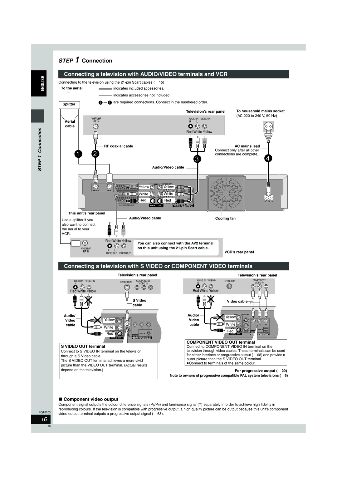
Connection
Recommended connection for your television
Connect the unit directly to the television
Connecting a television with 21-pin Scart terminal and VCR
AV1 terminal
Connecting a television with AUDIO/VIDEO terminals and VCR
Connection
Component video output
Video OUT terminal
Connecting a digital/satellite receiver or decoder
Connecting an amplifier or system component
White
Red
Preset Download Setup with Q Link functions
Channel reception settings
If the clock setting menu appears
Press Í DVD to turn the unit on
Auto-Setup Setup without Q Link functions
Country setting menu appears
Auto-Setup starts. This takes about 8 minutes
When Auto-Setup is complete, the following message appears
Selecting television type and aspect
Press Functions
To enjoy progressive video
Functions
When the following indicator appears on the unit’s display
Set up to match your television andremotecontrol
Television operation
Test by turning on the television and changing channels
Recording television programmes
Press ¥ REC to start recording
To pause recording
To stop recording
When using DVD-RW
Recording modes and approximate recording times
Before recording
After recording
Rec for High Speed dubbing
Flexible Recording
Press F Rec
Press 3, 4, 2, 1 to select Start and press Enter
Direct TV Recording
Playing while you are recording
Recording from digital/satellite receiver or decoder
Press Guide
Press F Timer
Press ShowView
To cancel recording when recording has Already begun
Timer recording
To release the unit from recording standby
VPS/PDC function
Manually programming timer recordings
Timer recording
Press PROG/CHECK
Refer to the control reference on
Making timer recordings on the television
Check, change or delete a programme
Playing recorded video contents/Playing play-only discs
Operations during play
Changing audio during play
Simple editing operations during play
Press Audio
Using menus to play MP3
Press TOP Menu
Press 3, 4 to select the track
Press 3, 4, 2, 1 to select a group
Playing still pictures JPEG/TIFF
Press HDD, DVD or SD
To select the drive
Press Return Press Functions
Useful functions during still picture play
Start Slide Show Slide Interval
Rotate
Zoom Zoom out
Using on-screen menus/FUNCTIONS window and Status message
Using on-screen menus
Using on-screen menus/FUNCTIONS window and Status message
Press Display
Functions window
Press 3, 4 to select an item Press Enter
Status messages
Press Status
Editing titles/chapters
Press Direct Navigator
Press 3, 4, 2, 1 to select the title
Press 3, 4, 2, 1 to select the chapter
Cancel Protection §
Title operations
Partial Erase
Chapter operations
Creating, editing and playing playlists
Creating playlists
Press 2, 1 to select the source title
Press
Editing and playing playlists/chapters
Playlist operations
Editing still pictures
Picture and folder operation
Transferring dubbing titles or playlists
Transferring dubbing titles or playlists
Transferring dubbing using the transferring dubbing list
One Touch Transfer dubbing
Set the transfer dubbing direction
Transferring dubbing titles or playlists
Set the recording mode
Register titles and playlists for transfer dubbing
Press 3, 4 to select Start Dubbing and press Enter
To stop transferring dubbing
Transferring dubbing a finalized
DVD-R, DVD-RW DVD-Video format
Set Dubbing Time
To edit the transferring dubbing list
Manual recording
Recording from a video cassette recorder
DV automatic recording DV Auto REC
Transferring dubbing still pictures
Register still pictures for transfer dubbing
Transferring dubbing still pictures
To register individual still pictures
Press 3, 4 to select Copy to
Press 2, 1 to select the drive
Press 3, 4, 2, 1 to select Copy
Still
Common procedures
Setting the protection
HDD, disc and card management
Providing a name for a disc
Erasing all the contents of a disc or card-Format
Erasing all titles and playlists-Erase all titles
Enabling discs to be played on other equipment
Press 3, 4 to select Auto-Play
Select and press Enter
Press 3, 4 to select Top Menu or
Show Enter Name screen
Entering text
Press Set
Changing the unit’s settings
Child Lock
Summary of settings
Changing the unit’s settings
Changing the unit’s settings
Disc
DTS
Changing the unit’s
Mpeg
Tabs Menus Options Underlined items are the factory presets
Others
Tuning
Press 3, 4 to select Manual and press Enter
Press 3, 4, 2
To select a
Auto-Setup Restart
Auto-Setup Restart, Download from TV
Press 3, 4, 2, 1 to select a country and press Enter
Download from TV
Clock settings
TV System
To change the setting all at once PAL!#NTSC
≥NTSC
Messages
Messages
On the television
On the unit’s display
Frequently asked questions
Set up
Asked
Cover
Troubleshooting guide
Troubleshooting guide
Low volume
Cannot switch audio
Presets from the television Startup is slow
Sound No sound
Troubleshooting guide
Preset
To reset the ratings level
Settings
To restore the unit if it freezes
Glossary
Glossary
Specifications
Norsk
Safety precautions
Index
Index
RGB
Memo
Warnung
Im Inneren des Gerätes
Inhaltsverzeichnis
Nützliche Funktionen
Zur Festplatte
Vorsichtsmaßnahmen zur Festplatte
Vorsichtsmaßnahmen
Pflege des Geräts
Handhabung von Disc und Karte
Handhabung von Disc und Karte / Pflege des Geräts
Einsetzen und Herausnehmen der SD-Karte
Hinweis zu PAL-progressiv-tauglichen Fernsehern
Fernsehern
Öffnen der Einsetzen der Karte Abdeckung
Verwendung einer DVD-R, DVD-RW oder +R in diesem Gerät
Einschränkungen bei DVD-Rs usw.§
Diesem Gerät
Verwendung einer DVD-R
Mitgeliefertes Zubehör
Informationen zur Fernbedienung
Fernbedienung
Mitgeliefertes Zubehör / Informationen zur
Festplatten-, Disc- und Karten-Information
Und
DVD-Video-Aufnahmeformat
DVD-Videoformat
Nur-Wiedergabe-Discs 12 cm/8 cm
Nicht abspielbare Discs
Festplatten-, Disc- und Karten-Information
Festplatten-, Disc- und Karten-Information
Mit diesem Gerät verwendbare Karten
Festplatten-, Disc- und Karten
Geeignete SD Memory Cards
Struktur der von diesem Gerät angezeigten Ordner
Anordnung der Bedienungselemente
Fernbedienung
Bedienungselemente
Der
Gerät
Display am Gerät
Anordnung der Bedienungselemente
Öffnen der Frontabdeckung
Schritt 1 Anschluss
Empfohlener Fernseher-Anschluss
Wenn das Gerät längere Zeit nicht verwendet Wird
Direkter Anschluss des Geräts an einen Fernseher
Anschluss
Buchse AV1
Schritt 1 Anschluss
Komponenten-Videoausgang
Buchse S Video OUT
Buchse Component Video OUT
Anschluss eines Digital-/Satellitenreceivers oder Decoders
Anschluss eines Verstärkers oder einer Systemanlage
Weiß
Rot
Sender-Übernahme Setup mit Q Link
Funktionen
Autom. Einstellung Setup ohne Q Link-Funktionen
So wird das Guide Plus+ System erneut Eingerichtet
Schritt 2 Einstellen der Empfangskanäle
Drücken Sie Enter
Wahl des Fernsehtyps und des Seitenverhältnisses
Drücken Sie Functions
Für ein progressives Videobild
Einrichten von Fernseher und Fernbedienung
Steuern des Fernsehers
Aufnehmen von Fernsehprogrammen
Aufnahmemodi und ungefähre Aufnahmezeiten
Vor dem Aufnehmen
Nach dem Aufnehmen
Festlegen der Aufnahmedauer-Aufnahme auf Tastendruck
Aufn. für High-Speed-Kopieren
Flexible Aufnahme
Drücken Sie F Rec
Aufnehmen von Fernsehprogrammen
Wiedergabe während der Aufnahme
TV-Direktaufnahme
Timeraufnahme
Verwendung der SHOWVIEW-Nummer für Timeraufnahmen
So schalten Sie den Aufnahme Bereitschaftsbetrieb aus
So brechen Sie die Aufnahme nach dem Start
VPS/PDC-Funktion
Ersatz-Aufnahme
Manuelle Programmierung von Timeraufnahmen
Weitere Timerprogramme, und
Timeraufnahme
Drücken Sie PROG/CHECK
Timeraufnahme mit dem Fernseher
Überprüfen, Ändern und Löschen von Programmen
Drücken Sie HDD oder DVD, um
Das Wiedergabe-Laufwerk zu wählen
Gerät, um die Lade auszufahren und
Eine Disc einzulegen
Bedienungsvorgänge während der Wiedergabe
Umschalten des Tons während der Wiedergabe
Einfache Editiervorgänge während der Wiedergabe
Drücken Sie Audio
Menügesteuerte Wiedergabe von MP3-Discs
Drücken Sie TOP Menu
Wählen Sie mit 3, 4, 2, 1 die
Gewünschte Gruppe aus, und drücken Sie Enter
Wiedergabe von Standbildern JPEG/TIFF
Drehen
Nützliche Funktionen bei der Standbildwiedergabe
Löschen
Bildschirmmenüs/FUNCTIONS-Fenster und Statusmeldungen
Verwendung der Bildschirmmenüs
Wählen Sie mit 3, 4 das Menü aus
Drücken Sie Display
FUNCTIONS-Fenster
Statusmeldungen
Drücken Sie Status
Statusmeldungen
Editieren von Titeln/Kapiteln
Editieren von Titeln/Kapiteln und Wiedergabe von Kapiteln
Wählen Sie mit 3, 4, 2, 1 den Titel aus
Drücken Sie SUB Menu
Titel-Einstellungen
Schutz aufheben §
Teile löschen
Kapitel-Einstellungen
Erstellen, Editieren und Wiedergeben von Playlisten
Playlisten erstellen
Drücken Sie 3, 4, 2, 1 zur Wahl der Playliste
Editieren und Wiedergeben von Playlisten/Kapiteln
Playlisten-Funktionen
Editieren von Standbildern
Bild- und Ordnereinstellvorgänge
Kopieren von Titeln und Playlisten
Kopieren von Titeln und Playlisten
Wählen Sie mit 2, 1 die Option Ja, und drücken Sie Enter
Überspielen mit der Überspielliste
Wählen Sie die Überspielrichtung
Kopieren von Titeln und Playlisten
Symbole und Funktionen der Überspielliste
Ändern des Aufnahmemodus
Registrieren von Titeln und Playlisten für das Überspielen
So stoppen Sie das Überspielen
Überspielen einer finalisierten DVD-R
DVD-RW DVD-Videoformat oder +R
Stellen Sie Kopierzeit ein
Von Titeln und
Aufnehmen von einem Videocassettenrecorder
Manuelles Aufnehmen
Automatische DV-Aufnahme
Aufnehmen von einem Videocassettenrecorder
Überspielen von Standbildern
Stellen Sie den Aufnahmemodus ein
Registrieren Sie die Standbilder für den Überspielbetrieb
So speichern Sie einzelne Standbilder
Überspielen aller Standbilder der Karte
So editieren Sie die Überspielliste
So wählen Sie einen anderen Ordner
Überspielen von Standbildern
Festplatten-, Disc- und Karten-Management
Allgemeine Bedienungsverfahren
Einstellen des Löschschutzes
Benennen einer Disc
Löschen aller Titel und Playlisten-Alle Titel löschen
Löschen des ganzen Disc- oder Karteninhalts-Formatieren
Nach den Schritten 1-3
So brechen Sie die Formatierung ab RAM
Auto-Play wählen, und drücken Sie
Wählen Sie mit 3, 4 die Option Top
Menu oder Titel 1, und drücken Sie
Finalisierung, und drücken Sie
Text eingeben
Zeigen Sie den Titel eingeben- Bildschirm an
Drücken Sie Übernehme
Text eingeben
Kindersicherung
Geräteeinstellungen
Ändern
Kindersicherung
Übersicht über die Einstellungen
Ändern der Geräteeinstellungen
Ändern der Geräteeinstellungen
Tabelle
Dynamikbereich-Kompression DVD-Vnur Dolby Digital
Sprachauswahl
Digital Audio Ausgang
PCM-Abwärtswandlung
Sonstige
Ändern der Belegung einzelner Programmpositionen
Neu erstellen
Datenübernahme von TV
Neu erstellen, Datenübernahme von TV
Liste der Fernsehempfangskanäle Fernsehkanal Kanalanzeige
Uhreinstellung
Fahren Sie mit 2, 1 die zu ändernden Positionen an
Ändern Sie die Einstellung mit 3
Drücken Sie am Ende der Einstellungen Enter
Gleichzeitiges Ändern aller Einstellungen PAL!#NTSC
Meldungen
Meldungen
Am Fernsehgerät
Im Display des Geräts
Häufig gestellte Fragen
Anlage Seite
Können in anderen Ländern gekaufte
ALL enthält
Fehlersuche
Fehlersuche
Ton Seite Kein Ton
Geringe Lautstärke
Tonverzerrungen
Der gewünschte Audiotyp wird
Fehlersuche
Geräts erscheint
Nicht richtig angezeigt
Beim Teile löschen-Vorgang
Können keine Start- und
Glossar
Glossar
Technische Daten
Sicherheitsmaßnahmen
Aufstellung
Spannung
Netzkabelschutz
Stichwortverzeichnis
Stichwortverzeichnis