Connecting Power Supply Wires
1.Remove the furnace control panel cover.
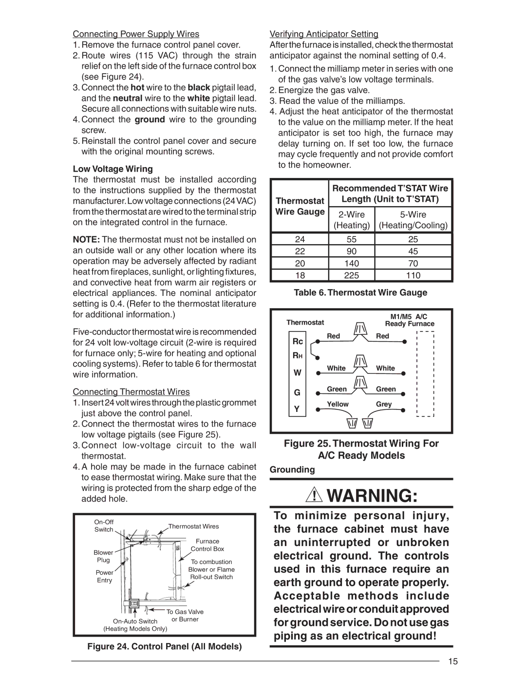
2.Route wires (115 VAC) through the strain relief on the left side of the furnace control box (see Figure 24).
3.Connect the hot wire to the black pigtail lead, and the neutral wire to the white pigtail lead. Secure all connections with suitable wire nuts.
4.Connect the ground wire to the grounding screw.
5.Reinstall the control panel cover and secure with the original mounting screws.
Low Voltage Wiring
The thermostat must be installed according to the instructions supplied by the thermostat manufacturer.Low voltage connections (24VAC) from the thermostat are wired to the terminal strip on the integrated control in the furnace.
NOTE: The thermostat must not be installed on an outside wall or any other location where its operation may be adversely affected by radiant heat from fi replaces, sunlight, or lighting fi xtures, and convective heat from warm air registers or electrical appliances. The nominal anticipator setting is 0.4. (Refer to the thermostat literature for additional information.)
Connecting Thermostat Wires
1.Insert 24 volt wires through the plastic grommet just above the control panel.
2.Connect the thermostat wires to the furnace low voltage pigtails (see Figure 25).
3.Connect
4.A hole may be made in the furnace cabinet to ease thermostat wiring. Make sure that the wiring is protected from the sharp edge of the added hole.
Thermostat Wires | ||
Switch | ||
| ||
| Furnace | |
Blower | Control Box | |
| ||
Plug | To combustion | |
| ||
Power | Blower or Flame | |
Entry | ||
|
![]()
![]()
![]()
![]()
![]()
![]()
![]() To Gas Valve
To Gas Valve
Figure 24. Control Panel (All Models)
Verifying Anticipator Setting
After the furnace is installed, check the thermostat anticipator against the nominal setting of 0.4.
1.Connect the milliamp meter in series with one of the gas valve’s low voltage terminals.
2.Energize the gas valve.
3.Read the value of the milliamps.
4.Adjust the heat anticipator of the thermostat to the value on the milliamp meter. If the heat anticipator is set too high, the furnace may delay turning on. If set too low, the furnace may cycle frequently and not provide comfort to the homeowner.
|
|
|
| Recommended T’STAT Wire | |
Thermostat |
| Length (Unit to T’STAT) | |||
Wire Gauge |
|
| |||
|
|
|
| ||
|
|
|
| (Heating) | (Heating/Cooling) |
|
|
|
|
|
|
24 |
|
| 55 | 25 | |
22 |
|
| 90 | 45 | |
20 |
|
| 140 | 70 | |
18 |
|
| 225 | 110 | |
| Table 6. Thermostat Wire Gauge | ||||
|
|
|
|
|
|
Thermostat |
|
| M1/M5 A/C | ||
|
| Ready Furnace | |||
|
|
| Red | Red | |
| Rc |
| |||
|
|
|
|
| |
| RH |
|
|
|
|
| W |
| White | White | |
|
|
|
|
| |
| G |
| Green | Green | |
|
|
|
|
| |
| Y |
| Yellow | Grey | |
|
|
|
|
| |
|
|
|
|
|
|
|
|
|
|
|
|
Figure 25. Thermostat Wiring For
A/C Ready Models
Grounding
![]() WARNING:
WARNING:
To minimize personal injury, the furnace cabinet must have an uninterrupted or unbroken electrical ground. The controls used in this furnace require an earth ground to operate properly. Acceptable methods include electrical wire or conduit approved for ground service. Do not use gas piping as an electrical ground!
15