38
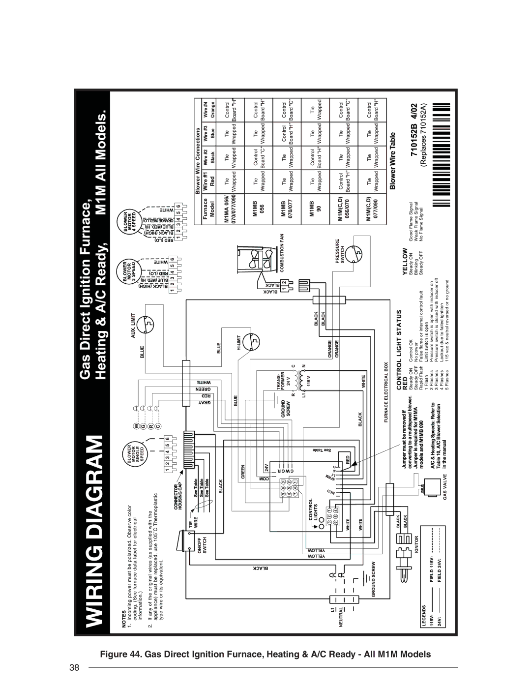
Figure 44. Gas Direct Ignition Furnace, Heating & A/C Ready - All M1M Models
WIRING DIAGRAM
1. Incoming power must be polarized. Observe color coding. (See furnace data label for electrical information.)
2. If any of the original wires (as supplied with the appliance) must be replaced, use 105˚C Thermoplastic type wire or its equivalent.
Steady ON | Control OK | Steady ON | Good Flame Signal | |
Steady OFF | No power | Blinking | Weak Flame Signal | |
Rapid Flash | False flame or internal control fault | Steady OFF | No Flame Signal | |
1 | Flash | Limit switch is open |
|
|
2 | Flashes | Pressure switch is open with inducer on |
|
|
3 | Flashes | Pressure switch is closed with inducer off |
|
|
4 | Flashes | Lockout due to failed ignition |
|
|
5 | Flashes | 115 vac & neutral reversed or no ground |
|
|