Location, size, and number of registers should be selected on the basis of best air distribution and fl oor plan of the home. The supply air must be delivered to the heated space by duct(s) secured to the furnace casing, running full size and without interruption.
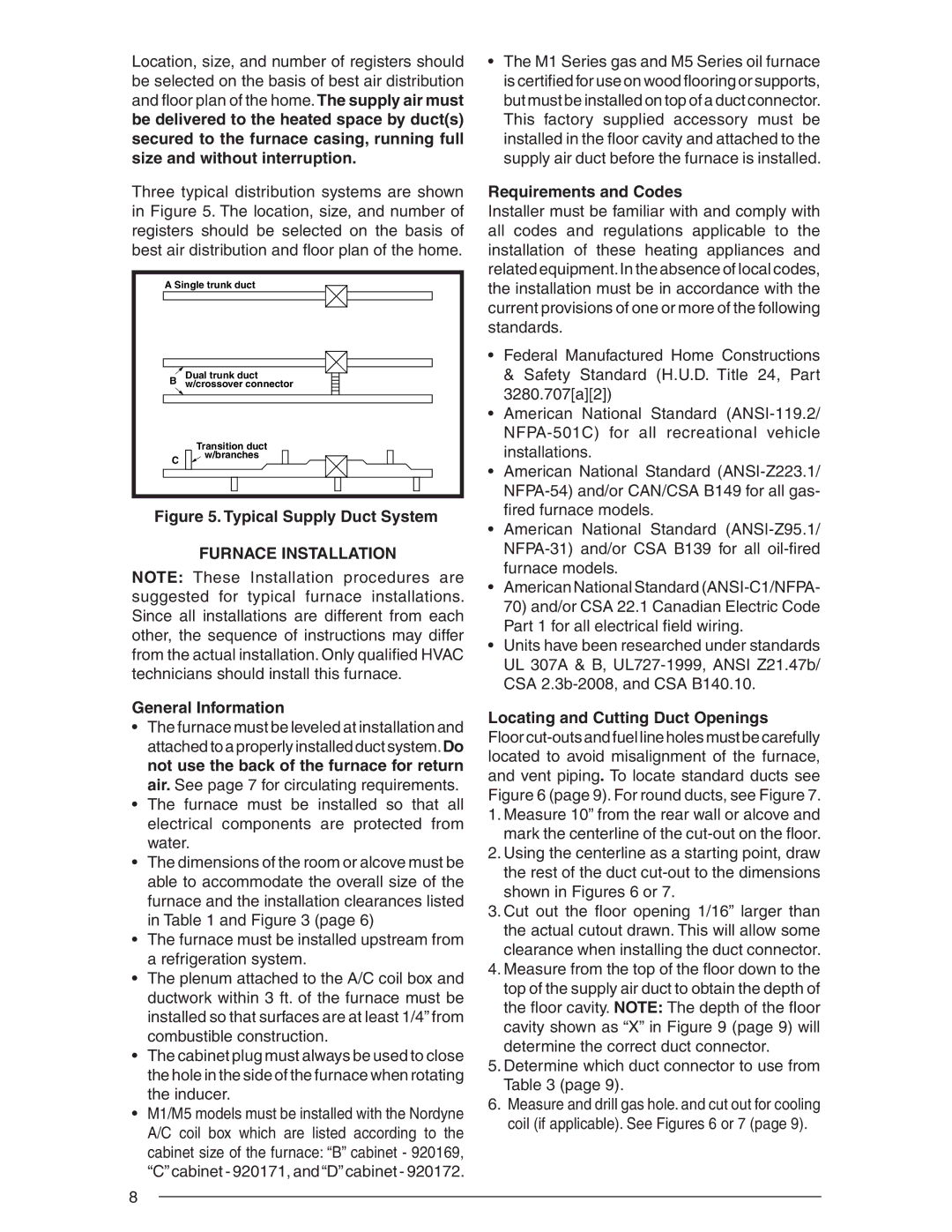
Three typical distribution systems are shown in Figure 5. The location, size, and number of registers should be selected on the basis of best air distribution and fl oor plan of the home.
A Single trunk duct | |
B | Dual trunk duct |
w/crossover connector | |
| Transition duct |
C | w/branches |
| |
Figure 5. Typical Supply Duct System
FURNACE INSTALLATION
NOTE: These Installation procedures are suggested for typical furnace installations. Since all installations are different from each other, the sequence of instructions may differ from the actual installation. Only qualifi ed HVAC technicians should install this furnace.
General Information
•The furnace must be leveled at installation and attached to a properly installed duct system.Do not use the back of the furnace for return air. See page 7 for circulating requirements.
•The furnace must be installed so that all electrical components are protected from water.
•The dimensions of the room or alcove must be able to accommodate the overall size of the furnace and the installation clearances listed in Table 1 and Figure 3 (page 6)
•The furnace must be installed upstream from a refrigeration system.
•The plenum attached to the A/C coil box and ductwork within 3 ft. of the furnace must be installed so that surfaces are at least 1/4” from combustible construction.
•The cabinet plug must always be used to close the hole in the side of the furnace when rotating the inducer.
•M1/M5 models must be installed with the Nordyne A/C coil box which are listed according to the cabinet size of the furnace: “B” cabinet - 920169, “C”cabinet - 920171, and “D”cabinet - 920172.
•The M1 Series gas and M5 Series oil furnace is certified for use on wood flooring or supports, but must be installed on top of a duct connector. This factory supplied accessory must be installed in the fl oor cavity and attached to the supply air duct before the furnace is installed.
Requirements and Codes
Installer must be familiar with and comply with all codes and regulations applicable to the installation of these heating appliances and related equipment.In the absence of local codes, the installation must be in accordance with the current provisions of one or more of the following standards.
•Federal Manufactured Home Constructions & Safety Standard (H.U.D. Title 24, Part 3280.707[a][2])
•American National Standard
•American National Standard
•American National Standard
•American National Standard
•Units have been researched under standards UL 307A & B,
Locating and Cutting Duct Openings
Floor
1.Measure 10” from the rear wall or alcove and mark the centerline of the
2.Using the centerline as a starting point, draw the rest of the duct
3.Cut out the fl oor opening 1/16” larger than the actual cutout drawn. This will allow some clearance when installing the duct connector.
4.Measure from the top of the fl oor down to the top of the supply air duct to obtain the depth of the fl oor cavity. NOTE: The depth of the fl oor cavity shown as “X” in Figure 9 (page 9) will determine the correct duct connector.
5.Determine which duct connector to use from Table 3 (page 9).
6.Measure and drill gas hole. and cut out for cooling coil (if applicable). See Figures 6 or 7 (page 9).
8