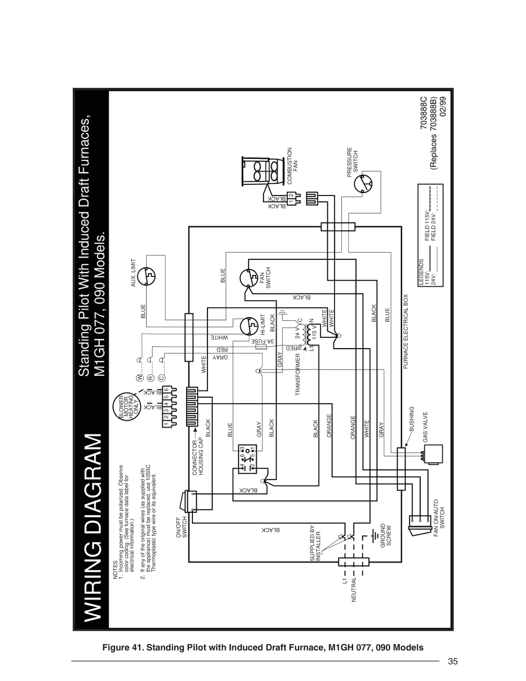
Figure 41. Standing Pilot with Induced Draft Furnace, M1GH 077, 090 Models
35
WIRING DIAGRAM |
|
|
|
|
| Standing Pilot With Induced Draft Furnaces, | ||||||||||
|
|
|
|
| M1GH 077, 090 Models. |
| ||||||||||
NOTES |
|
|
|
|
|
|
|
|
|
|
|
|
|
|
|
|
1. Incoming power must be polarized. Observe |
|
| BLOWER |
|
|
|
|
|
|
|
| |||||
color coding. (See furnace data label for |
|
| MOTOR |
|
|
|
|
| AUX. LIMIT |
|
| |||||
electrical information.) |
|
|
|
| HEATING |
|
|
|
|
|
|
| ||||
2. If any of the original wires (as supplied with |
|
|
| ONLY |
|
| W |
| BLUE |
|
|
|
| |||
|
|
| BLACK |
| BLACK |
|
|
|
|
| ||||||
|
|
|
|
|
|
|
|
|
| |||||||
the appliance) must be replaced, use 105˚C |
|
|
|
| R |
|
|
|
|
|
| |||||
Thermoplastic type wire or its equivalent. |
|
|
|
|
|
|
|
|
|
|
|
|
| |||
|
|
|
|
|
|
|
|
|
|
|
|
|
| |||
|
|
|
| 1 | 2 | 3 | 4 | 5 | 6 | C |
|
|
|
|
|
|
|
|
|
|
|
|
|
|
|
|
| ||||||
ON/OFF |
|
|
|
|
|
|
|
|
|
|
|
|
|
|
|
|
SWITCH |
|
|
|
|
|
|
|
|
|
|
|
|
|
|
|
|
|
| CONNECTOR |
|
|
|
|
|
|
|
|
|
|
|
| ||
|
| HOUSING CAP |
|
|
|
|
| WHITE |
|
|
|
|
|
| ||
|
|
|
| BLACK |
|
|
|
|
|
|
|
|
|
| ||
|
|
|
|
|
|
|
| GRAY RED |
| WHITE |
|
|
|
| ||
|
|
|
| BLUE |
|
|
|
|
|
|
| BLUE |
|
| ||
|
|
|
|
|
|
|
|
|
|
|
|
|
|
| ||
BLACK | BLACK |
|
|
|
|
|
|
|
| FUSE3A |
|
|
| BLACK BLACK |
| |
4 | 6 | 3 |
|
|
|
|
|
|
|
|
|
| ||||
|
|
|
|
|
|
|
|
|
|
|
|
|
| |||
|
| 2 | 5 | 1 |
|
|
|
|
|
|
|
|
|
|
|
|
|
|
|
| GRAY |
|
|
|
|
|
|
|
| FAN |
|
| |
|
|
|
|
|
|
|
|
|
|
|
|
|
|
| ||
|
|
|
| BLACK |
|
|
|
|
|
| BLACK |
| SWITCH |
|
| |
|
|
|
|
|
|
|
| GRAY |
|
|
|
|
| |||
|
|
|
|
|
|
|
|
|
|
|
|
|
|
| FAN | |
|
|
|
|
|
|
|
|
|
| RED |
|
|
|
| 1 2 | |
|
|
|
|
|
|
|
| TRANSFORMER R |
| 24 V C | BLACK |
| COMBUSTION | |||
|
|
|
|
|
|
|
|
|
|
|
| |||||
|
|
|
|
|
|
|
|
|
|
|
|
| ||||
SUPPLIED BY |
|
|
| BLACK |
|
|
|
|
| L1 | 115 V N |
|
|
|
| |
INSTALLER |
|
|
|
|
|
|
|
|
|
|
| WHITE |
|
|
|
|
|
|
|
| ORANGE |
|
|
|
|
|
|
|
|
| |||
|
|
|
|
|
|
|
|
| WHITE |
|
|
|
| |||
|
|
|
|
|
|
|
|
|
|
|
|
|
|
|
| |
L1 |
|
|
|
|
|
|
|
|
|
|
|
|
|
|
| PRESSURE |
NEUTRAL |
|
|
| ORANGE |
|
|
|
|
|
|
|
|
|
| ||
|
|
|
|
|
|
|
|
|
|
|
|
| SWITCH | |||
|
|
|
| WHITE |
|
|
|
|
|
|
| BLACK |
|
|
|
|
|
|
|
| GRAY |
|
|
|
|
|
|
|
|
|
|
| |
GROUND |
|
|
|
|
|
|
|
|
|
| BLUE |
|
|
|
| |
SCREW |
|
|
|
|
|
|
|
|
|
|
|
|
|
|
| |
|
|
|
| BUSHING |
|
|
| FURNACE ELECTRICAL BOX |
|
|
| |||||
|
|
|
|
|
|
|
|
|
|
|
|
|
| |||
|
|
|
| GAS VALVE |
|
|
|
|
|
|
| LEGENDS |
| 703888C | ||
|
|
|
|
|
|
|
|
|
|
| 115V: | FIELD 115V: | ||||
FAN ON/AUTO |
|
|
|
|
|
|
|
|
|
|
|
|
| 24V: | FIELD 24V: | (Replaces 703888B) |
SWITCH |
|
|
|
|
|
|
|
|
|
|
|
|
|
|
| 02/99 |