For L.P. gas, pressure to the gas valve must be more than 11” W.C. but not more than 13” W.C. Pressure is reduced to 10” W.C. by the pressure regulator in the gas valve.
![]() CAUTION:
CAUTION:
Furnace conversion must be per- formed by a qualified technician. Improper conversion can cause unsafe operation, explosion, fire and/or asphyxiation.
Oil Tank and Piping Installation
The following procedures are recommended as good practice. However, requirements of local codes and ordinances, H.U.D. Manufactured Home and Safety Standards or National Fire Protection Association must be satisfi ed, where they apply, for an approved installation.
•Use a tank capacity suitable for the application with a weatherproof, capped fi ll opening and a shielded vent to let in air as fuel is used.
•The inside of the tank must be clean before fi lling. All water, rust, sediment, and debris must be fl ushed out.
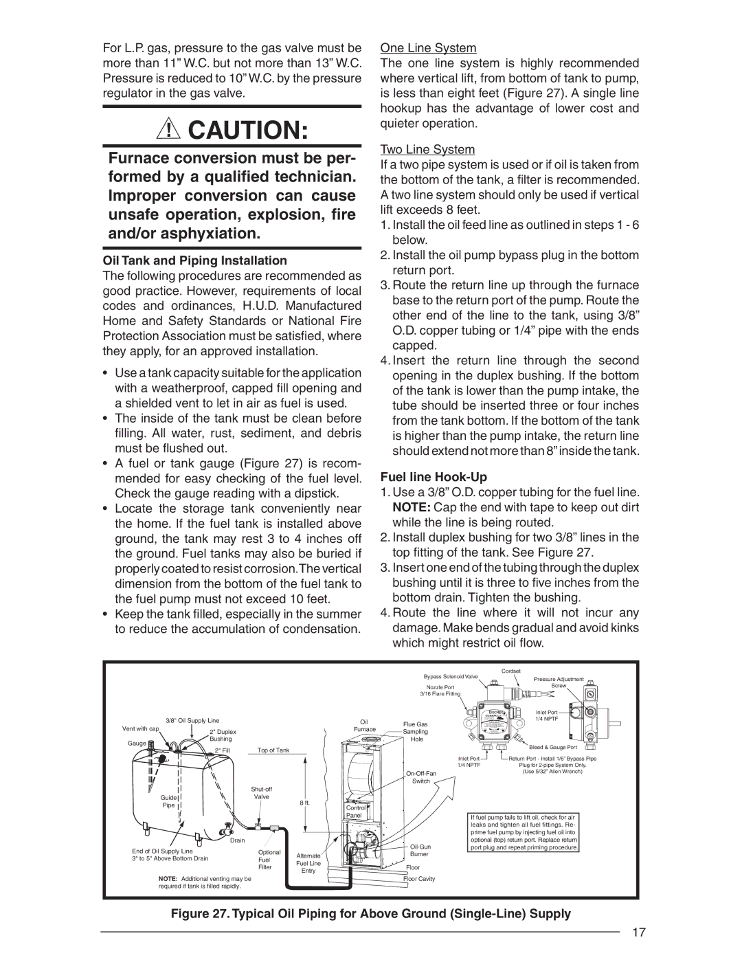
•A fuel or tank gauge (Figure 27) is recom- mended for easy checking of the fuel level. Check the gauge reading with a dipstick.
•Locate the storage tank conveniently near the home. If the fuel tank is installed above ground, the tank may rest 3 to 4 inches off the ground. Fuel tanks may also be buried if properly coated to resist corrosion.The vertical dimension from the bottom of the fuel tank to the fuel pump must not exceed 10 feet.
•Keep the tank fi lled, especially in the summer to reduce the accumulation of condensation.
One Line System
The one line system is highly recommended where vertical lift, from bottom of tank to pump, is less than eight feet (Figure 27). A single line hookup has the advantage of lower cost and quieter operation.
Two Line System
If a two pipe system is used or if oil is taken from the bottom of the tank, a fi lter is recommended. A two line system should only be used if vertical lift exceeds 8 feet.
1.Install the oil feed line as outlined in steps 1 - 6 below.
2.Install the oil pump bypass plug in the bottom return port.
3.Route the return line up through the furnace base to the return port of the pump. Route the other end of the line to the tank, using 3/8” O.D. copper tubing or 1/4” pipe with the ends capped.
4.Insert the return line through the second opening in the duplex bushing. If the bottom of the tank is lower than the pump intake, the tube should be inserted three or four inches from the tank bottom. If the bottom of the tank is higher than the pump intake, the return line should extend not more than 8” inside the tank.
Fuel line Hook-Up
1.Use a 3/8” O.D. copper tubing for the fuel line. NOTE: Cap the end with tape to keep out dirt while the line is being routed.
2.Install duplex bushing for two 3/8” lines in the top fi tting of the tank. See Figure 27.
3.Insert one end of the tubing through the duplex bushing until it is three to fi ve inches from the bottom drain. Tighten the bushing.
4.Route the line where it will not incur any damage. Make bends gradual and avoid kinks which might restrict oil fl ow.
Bypass Solenoid Valve
Nozzle Port
3/16 Flare Fitting
Cordset
Pressure Adjustment
Screw
3/8" Oil Supply Line |
|
| Oil | Flue Gas | |
Vent with cap |
|
|
| Furnace | |
2" Duplex |
|
| Sampling | ||
|
|
|
| ||
Gauge | Bushing |
|
|
| Hole |
|
|
|
|
| |
| 2" Fill | Top of Tank |
|
|
|
|
|
|
|
| |
|
|
|
|
| Switch |
|
|
|
| ||
Guide |
| Valve | 8 ft. |
|
|
Pipe |
|
| Control |
| |
|
|
|
| ||
|
|
|
|
| |
|
|
|
| Panel |
|
| Drain |
|
|
| |
End of Oil Supply Line |
| Optional |
|
| |
| Alternate |
| Burner | ||
3" to 5" Above Bottom Drain |
| Fuel |
| ||
| Fuel Line |
|
| ||
|
| Filter |
| Floor | |
|
| Entry |
| ||
|
|
|
|
| |
NOTE: Additional venting may be |
|
|
| Floor Cavity | |
required if tank is filled rapidly. |
|
|
|
| |
| Beckett | Inlet Port |
| 1/4 NPTF | |
4 | GPH |
|
NO. 2 & LIGHTER FUEL |
| |
3 GPH |
| |
|
| Bleed & Gauge Port |
Inlet Port |
| Return Port - Install 1/6” Bypass Pipe |
1/4 NPTF |
| Plug for |
|
| (Use 5/32” Allen Wrench) |
If fuel pump fails to lift oil, check for air leaks and tighten all fuel fittings. Re- prime fuel pump by injecting fuel oil into optional (top) return port. Replace return port plug and repeat priming procedure.
Figure 27. Typical Oil Piping for Above Ground (Single-Line) Supply
17