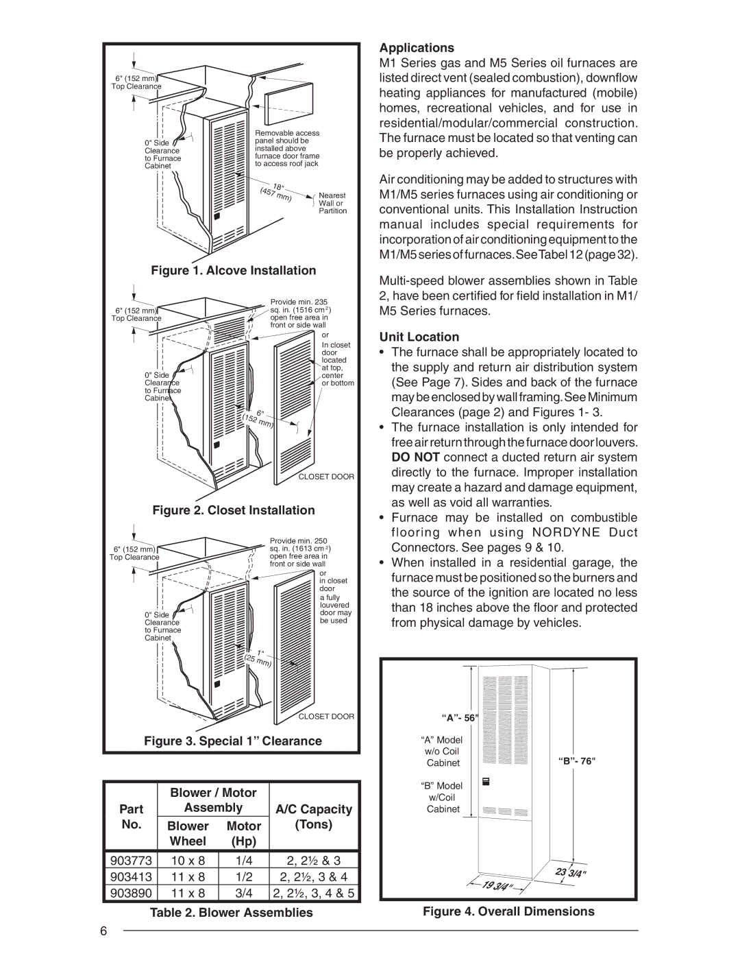
6" (152 mm)
Top Clearance
0" Side Clearance to Furnace Cabinet
Removable access panel should be installed above furnace door frame to access roof jack
18" |
| |
(457 | mm) | Nearest |
|
| Wall or |
|
| Partition |
Applications
M1 Series gas and M5 Series oil furnaces are listed direct vent (sealed combustion), downfl ow heating appliances for manufactured (mobile) homes, recreational vehicles, and for use in residential/modular/commercial construction. The furnace must be located so that venting can be properly achieved.
Air conditioning may be added to structures with M1/M5 series furnaces using air conditioning or conventional units. This Installation Instruction manual includes special requirements for incorporation of air conditioning equipment to the M1/M5 series of furnaces.SeeTabel 12 (page 32).
Figure 1. Alcove Installation
6" (152 mm)
Top Clearance
0" Side Clearance to Furnace Cabinet
Provide min. 235 sq. in. (1516 cm 2 )
open free area in
front or side wall
or
In closet door
located at top, center
or bottom
(152 | 6" | |
mm) | ||
|
Unit Location
• The furnace shall be appropriately located to |
the supply and return air distribution system |
(See Page 7). Sides and back of the furnace |
may be enclosed by wall framing.See Minimum |
Clearances (page 2) and Figures 1- 3. |
• The furnace installation is only intended for |
free air return through the furnace door louvers. |
DO NOT connect a ducted return air system |
CLOSET DOOR
Figure 2. Closet Installation
directly to the furnace. Improper installation |
may create a hazard and damage equipment, |
as well as void all warranties. |
• Furnace may be installed on combustible |
flooring when using NORDYNE Duct |
6" (152 mm)
Top Clearance
0" Side Clearance to Furnace Cabinet
Provide min. 250 sq. in. (1613 cm 2) open free area in front or side wall
or
in closet
door
a fully louvered door may be used
(25 | 1" | |
mm) | ||
|
CLOSET DOOR
Connectors. See pages 9 & 10. |
• When installed in a residential garage, the |
furnace must be positioned so the burners and |
the source of the ignition are located no less |
than 18 inches above the fl oor and protected |
from physical damage by vehicles. |
“A”- 56" |
Figure 3. Special 1” Clearance
| Blower / Motor |
| |
Part | Assembly | A/C Capacity | |
No. | Blower | Motor | (Tons) |
| Wheel | (Hp) |
|
903773 | 10 x 8 | 1/4 | 2, 2½ & 3 |
903413 | 11 x 8 | 1/2 | 2, 2½, 3 & 4 |
903890 | 11 x 8 | 3/4 | 2, 2½, 3, 4 & 5 |
Table 2. Blower Assemblies
“A” Model |
|
w/o Coil | “B”- 76" |
Cabinet | |
“B” Model |
|
w/Coil |
|
Cabinet |
|
23 3/4"
![]() 19 3/4"
19 3/4" ![]()
![]()
Figure 4. Overall Dimensions
6