34
WIRING DIAGRAM | Gas Atmospheric Furnaces, M1GH 056, 070 |
Figure 40
NOTES
1.Incoming power must be polarized. Observe color coding. (See furnace data label for electrical information.)
2.If any of the original wires (as supplied with the appliance) must be replaced, use 105˚C Thermoplastic type wire or its equivalent.
BLOWER
MOTOR
HEATING
ONLY
BLACK |
| BLACK |
|
|
| ||
|
| ||
|
|
1 2 3 4 5 6
W![]()
R![]() C
C![]()
COMMON
WHITE
AUX. LIMIT
BLUE
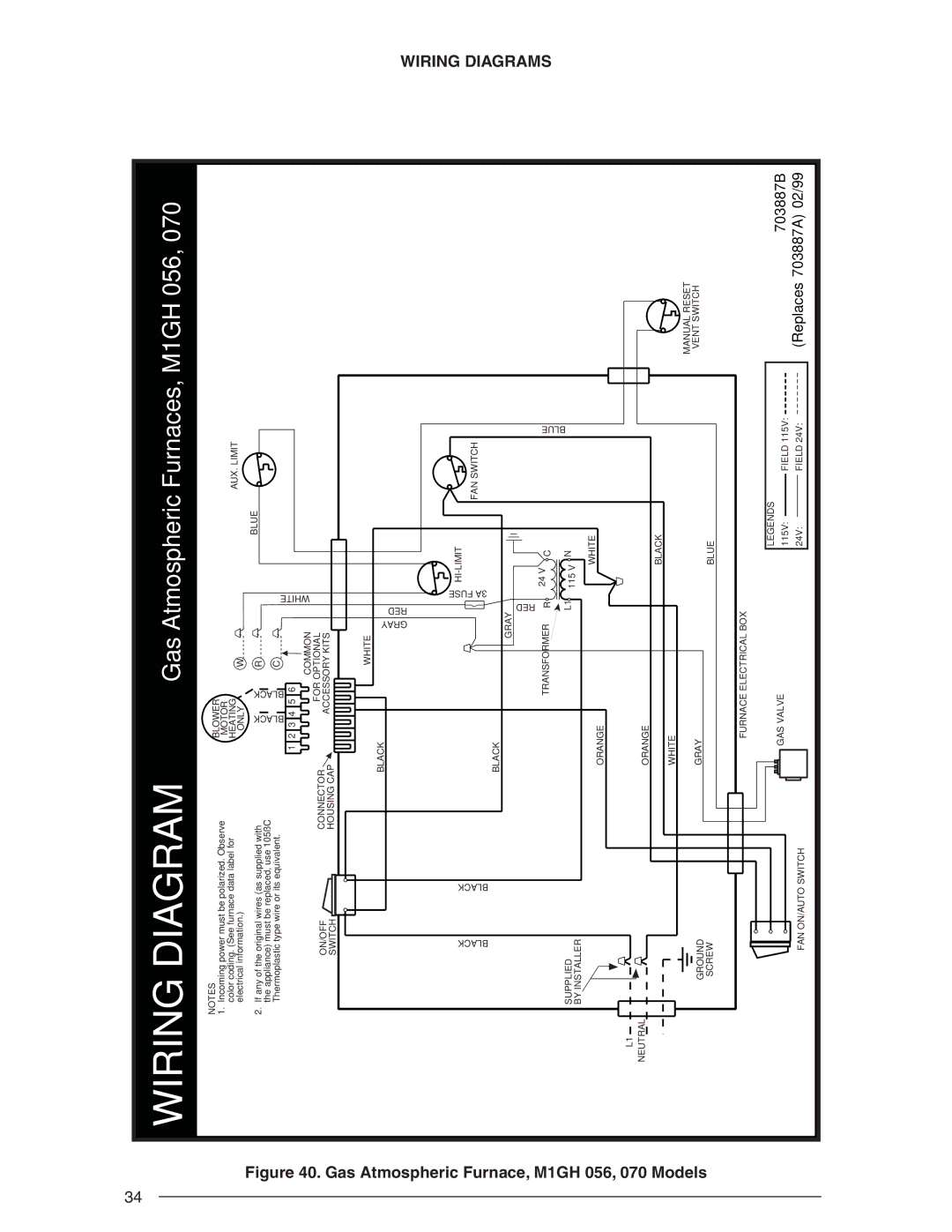
. Gas Atmospheric Furnace, M1GH 056, 070
L1
NEUTRAL
ON/OFF |
| CONNECTOR | FOR OPTIONAL |
|
| ACCESSORY KITS |
| ||
SWITCH |
| HOUSING CAP |
|
|
|
|
| WHITE |
|
|
| BLACK | GRAY | RED |
|
|
| ||
BLACK | BLACK | BLACK |
| 3A FUSE |
|
| GRAY | ||
|
|
| ||
|
|
| TRANSFORMER | RED |
|
|
| R | |
SUPPLIED |
|
|
| L1 |
BY INSTALLER |
|
|
|
|
|
| ORANGE |
|
|
|
| ORANGE |
|
|
24 V ![]() C
C
115 V ![]() N WHITE
N WHITE
FAN SWITCH
BLUE
WIRING DIAGRAMS
Models
| WHITE |
GROUND | GRAY |
SCREW |
|
| FURNACE ELECTRICAL BOX |
| GAS VALVE |
FAN ON/AUTO SWITCH |
|
BLACK
BLUE
LEGENDS |
| |||
115V: |
|
| FIELD 115V: | |
|
| |||
24V: |
|
| FIELD 24V: | |
| ||||
MANUAL RESET
VENT SWITCH
703887B
(Replaces 703887A) 02/99