4.The four warning tags supplied must be installed as follows:
•To weather cap
•To fuel line connection point (Gas) or furnace burner (Oil)
•To furnace fl ame observation door (Gas or Oil)
•To furnace wall thermostat
5.
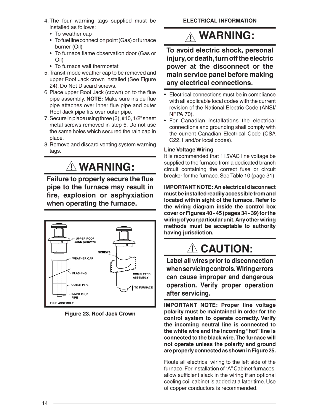
6.Place upper Roof Jack (crown) on to the fl ue pipe assembly. NOTE: Make sure inside fl ue pipe attaches over inner fl ue pipe and outer Roof Jack pipe fi ts over outer pipe.
7.Secure in place using three (3), #10, 1/2”sheet metal screws removed in step 5. Do not use the same holes which secured the rain cap in place.
8.Remove and discard venting system warning tags.
![]() WARNING:
WARNING:
Failure to properly secure the flue pipe to the furnace may result in fire, explosion or asphyxiation when operating the furnace.
![]()
![]()
![]() UPPER ROOF
UPPER ROOF
JACK (CROWN)
SCREWS
WEATHER CAP |
|
FLASHING | COMPLETED |
| |
| ASSEMBLY |
OUTER PIPE | TO FURNACE |
|
INNER FLUE
PIPE
FLUE ASSEMBLY
Figure 23. Roof Jack Crown
ELECTRICAL INFORMATION
![]() WARNING:
WARNING:
To avoid electric shock, personal injury,or death,turn off the electric power at the disconnect or the main service panel before making any electrical connections.
•Electrical connections must be in compliance with all applicable local codes with the current revision of the National Electric Code (ANSI/ NFPA 70).
•For Canadian installations the electrical connections and grounding shall comply with the current Canadian Electrical Code (CSA C22.1 and/or local codes).
Line Voltage Wiring
It is recommended that 115VAC line voltage be supplied to the furnace from a dedicated branch circuit containing the correct fuse or circuit breaker for the furnace. See Table 10 (page 31).
IMPORTANT NOTE: An electrical disconnect must be installed readily accessible from and located within sight of the furnace. Refer to the wiring diagram inside the control box cover or Figures 40 - 45 (pages 34 - 39) for the wiring of your particular unit. Any other wiring methods must be acceptable to authority having jurisdiction.
![]() CAUTION:
CAUTION:
Label all wires prior to disconnection when servicing controls. Wiring errors can cause improper and dangerous operation. Verify proper operation after servicing.
IMPORTANT NOTE: Proper line voltage polarity must be maintained in order for the control system to operate correctly. Verify the incoming neutral line is connected to the white wire and the incoming “hot” line is connected to the black wire.The furnace will not operate unless the polarity and ground are properly connected as shown in Figure 25.
Route all electrical wiring to the left side of the furnace. For installation of “A” Cabinet furnaces, allow suffi cient slack in the wiring if an optional cooling coil cabinet is added at a later time. Use of copper conductors is recommended.
14