EN 20 |
| 4. |
|
| DVD963SA | ||||
4.3 | Service Hints |
|
| 4.3.3 | ComPair | ||||
4.3.1 Switched Mode Power Supply |
|
| For assistance with the repair process of the monoboard an | ||||||
|
|
|
|
|
|
|
|
| electronic fault finding guidance has been developed. This |
| The power supply unit has to be replaced in case of failure. The |
| program is called ComPair. | ||||||
|
| This ComPair program is available on CDROM. | |||||||
| schematic provided in the manual is only for information and no |
| |||||||
|
| The version of the CDROM for repair of the monoboard is V1.3 | |||||||
| service parts will be available. |
|
| ||||||
|
|
| or higher and can be ordered with codenumber 4822 727 | ||||||
|
|
|
|
|
|
|
|
| |
4.3.2 | DVD Module |
|
|
| 21637. This is an update CDROM, so when the ComPair | ||||
|
|
| CDROM is used for the first time, one has to install the ComPair | ||||||
|
|
|
|
|
|
|
|
| |
| This module can be repaired as follows: |
|
| Engine CDROM V1.2 first. | |||||
|
|
| The V1.2 CDROM can be ordered with code number 4822 727 | ||||||
| 1. The VAL6011/14 is a combination of loading mechanism |
| 21634 and has to registered after instalation. The procedure for | ||||||
|
| registration is explained in the help file of the program and in | |||||||
|
| and |
| the CDROM booklet. | |||||
|
| case of failure, it has to be replaced with a new loader |
| The cable to connect the monoboard with a PC can be ordered | |||||
|
| VAL6011/14. |
|
|
| with codenumber: 3122 785 90017. | |||
|
| Note: When replacing with a new VAL6011/14, two solder |
| All the hardware and software requirements of the systems, | |||||
|
|
| necessary for working with ComPair, are described on the | ||||||
|
| joints have to be removed after connecting the OPU flex foil |
| CDROM. | |||||
|
| to the mono board. |
|
|
| ||||
|
| The solder joints, which shortcircuits the laser diodes to | 4.3.4 | Service Positions | |||||
|
|
|
|
|
|
|
| ||
ground, are for protection against ESD. Refer to figures 2- |
| |
5 and | Refer to dismantling instructions for dismounting of the board. | |
2. The mono board has to be repaired down to component | ||
Figures | ||
level. Repair handling of the monoboard requires a | ||
recommended during repair of the boards. | ||
workshop with sophisticated desoldering tools. | ||
|
Figure 4-3 Solder joints
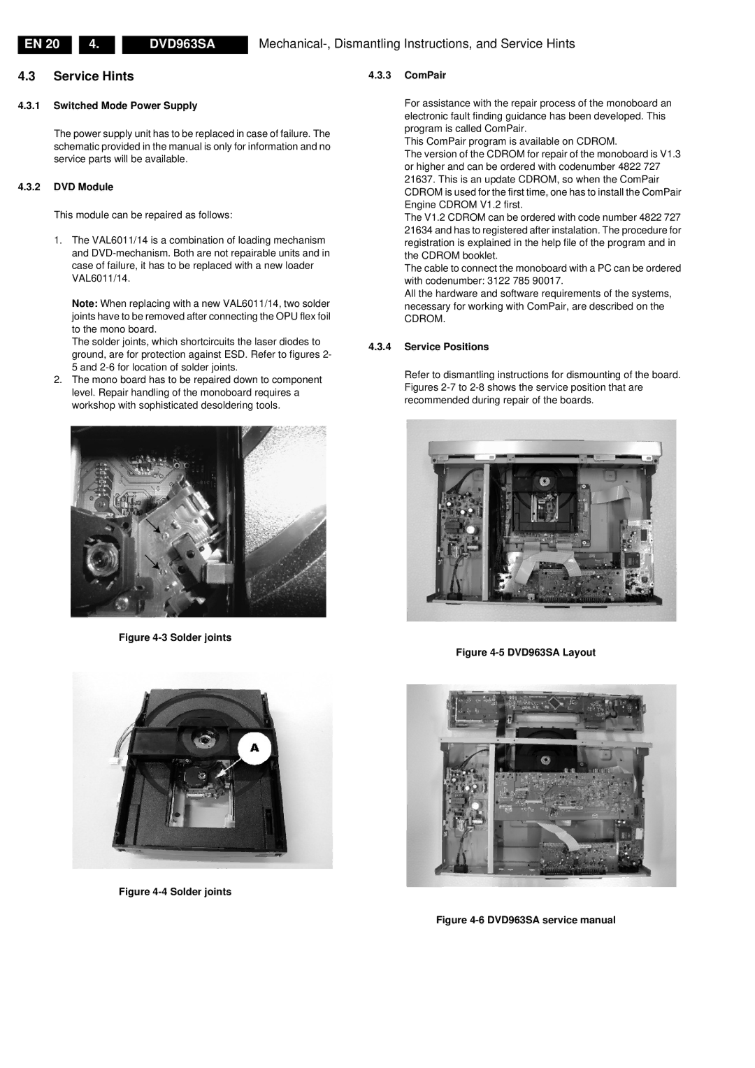
Figure 4-5 DVD963SA Layout
Figure 4-4 Solder joints
Figure