Connect Peripheral Equipment
There is a wide range of audio and video equipment that can be connected to your TV. The following connection diagrams show you how to connect them.
Note: EXT. 1 can handle CVBS and RGB, EXT. 2 CVBS, RGB and Y/C, EXT. 3 and EXT. 4 only CVBS.
It is preferred to connect peripherals with RGB output to EXT. 1 or 2 as RGB provides a better picture quality. If your recorder is provided with the EasyLink function, it should be connected to EXT. 2 to benefit from the EasyLink functionality.
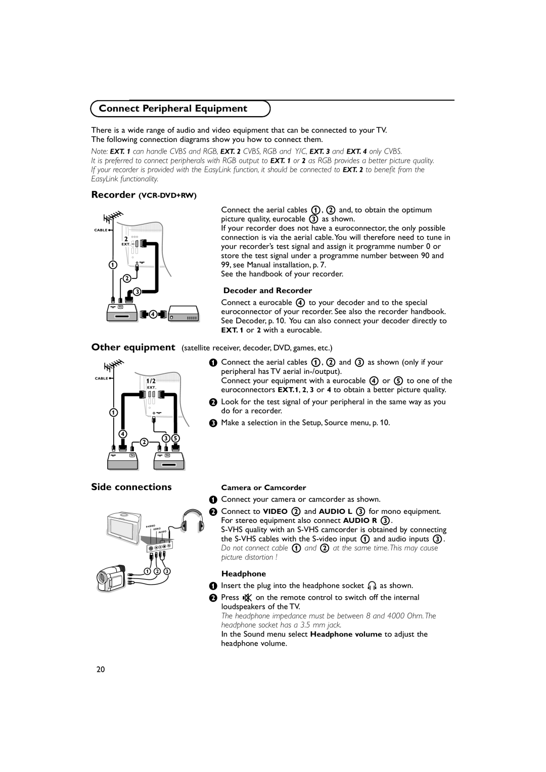
Recorder
CABLE ![]()
2
EXT. ![]()
1![]()
![]()
2
3
4
Connect the aerial cables 1, 2 and, to obtain the optimum picture quality, eurocable 3 as shown.
If your recorder does not have a euroconnector, the only possible connection is via the aerial cable.You will therefore need to tune in your recorder’s test signal and assign it programme number 0 or store the test signal under a programme number between 90 and 99, see Manual installation, p. 7.
See the handbook of your recorder.
Decoder and Recorder
Connect a eurocable 4 to your decoder and to the special euroconnector of your recorder. See also the recorder handbook. See Decoder, p. 10. You can also connect your decoder directly to EXT. 1 or 2 with a eurocable.
Other equipment (satellite receiver, decoder, DVD, games, etc.)
CABLE ![]()
1
![]() 1/2
1/2![]()
![]()
![]()
![]()
![]()
![]()
![]()
![]()
![]()
![]()
![]()
![]()
![]()
![]()
![]()
![]()
![]()
![]()
![]()
![]()
![]()
![]()
![]()
![]()
![]()
![]()
![]()
![]()
![]()
![]()
![]() EXT.
EXT.
&Connect the aerial cables 1, 2 and 3 as shown (only if your peripheral has TV aerial
Connect your equipment with a eurocable 4 or 5 to one of the euroconnectors EXT.1, 2, 3 or 4 to obtain a better picture quality.
éLook for the test signal of your peripheral in the same way as you do for a recorder.
“Make a selection in the Setup, Source menu, p. 10.
4
2
3 5
Side connections
Camera or Camcorder
S•VIDEO VIDEO AUDIO
&Connect your camera or camcorder as shown.
éConnect to VIDEO 2 and AUDIO L 3 for mono equipment. For stereo equipment also connect AUDIO R 3.
1 | 2 | 3 | Headphone |
|
|
|
&Insert the plug into the headphone socket L as shown.
éPress ¬ on the remote control to switch off the internal loudspeakers of the TV.
The headphone impedance must be between 8 and 4000 Ohm. The headphone socket has a 3.5 mm jack.
In the Sound menu select Headphone volume to adjust the headphone volume.
20