Additional Information
Connection Diagram
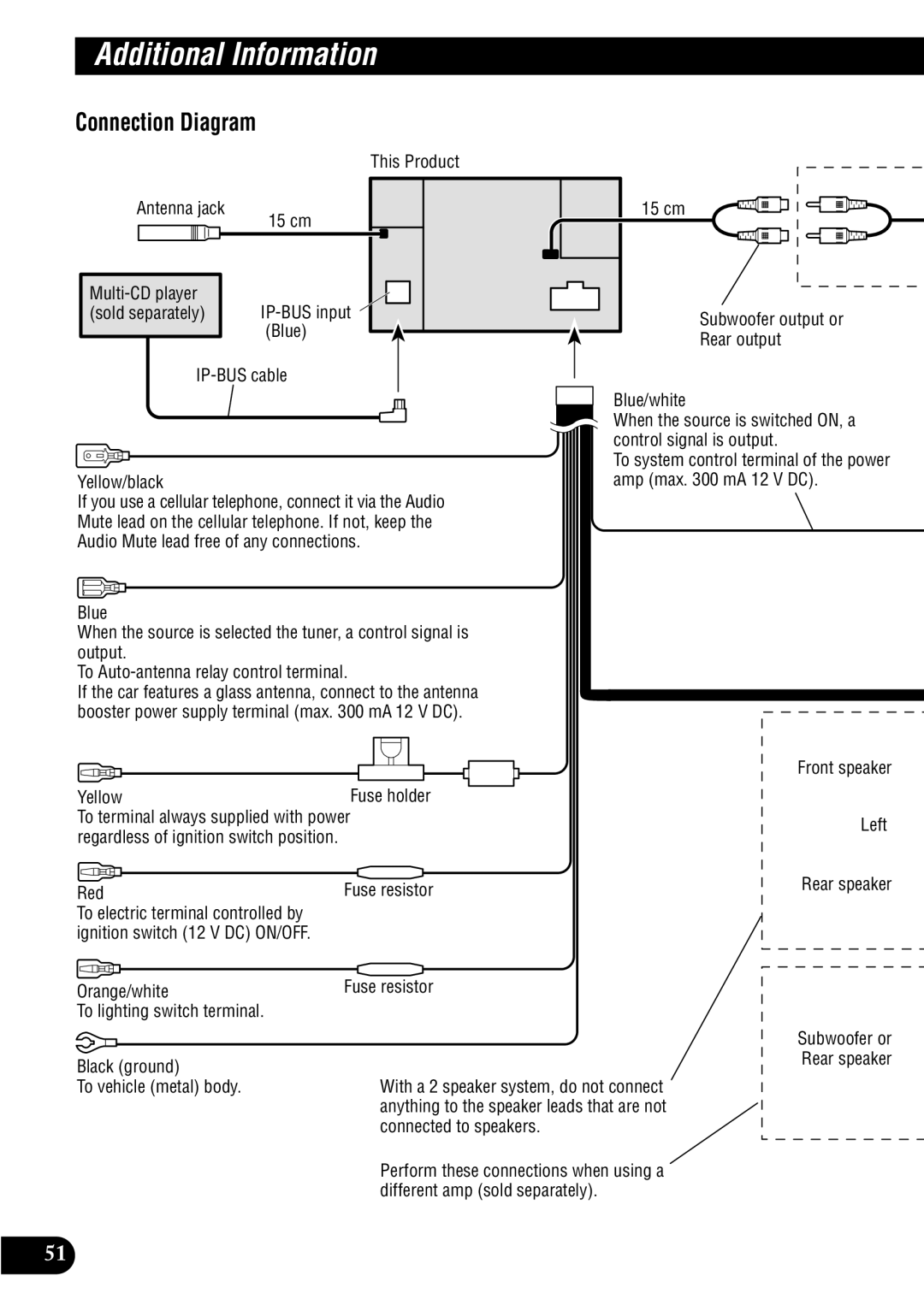
This Product
Antenna jack | 15 cm |
|
|
|
|
|
|
| ||||||
|
|
|
|
|
|
|
|
|
|
|
|
|
| |
|
|
|
|
|
|
|
|
|
|
|
|
|
|
|
|
|
|
|
|
|
|
| |||||||
|
|
|
|
|
|
|
| |||||||
(sold separately) |
|
|
|
|
|
|
|
| ||||||
|
|
|
|
|
|
| (Blue) |
|
|
|
|
|
|
|
|
|
|
|
|
|
|
|
| ||||||
|
|
|
|
|
|
|
|
|
|
|
|
|
|
|
|
|
|
|
|
|
|
|
|
|
|
|
|
|
|
Yellow/black
If you use a cellular telephone, connect it via the Audio Mute lead on the cellular telephone. If not, keep the Audio Mute lead free of any connections.
Blue
When the source is selected the tuner, a control signal is output.
To
If the car features a glass antenna, connect to the antenna booster power supply terminal (max. 300 mA 12 V DC).
Yellow | Fuse holder |
To terminal always supplied with power | |
regardless of ignition switch position. |
|
Red | Fuse resistor |
To electric terminal controlled by |
|
ignition switch (12 V DC) ON/OFF. |
|
15 cm
Subwoofer output or
Rear output
Blue/white
When the source is switched ON, a control signal is output.
To system control terminal of the power amp (max. 300 mA 12 V DC).
Front speaker
Left
Rear speaker
Orange/white
To lighting switch terminal.
Black (ground)
To vehicle (metal) body.
Fuse resistor
With a 2 speaker system, do not connect anything to the speaker leads that are not connected to speakers.
Perform these connections when using a different amp (sold separately).
Subwoofer or Rear speaker
51