Installation and Connections
Control Cord Connection
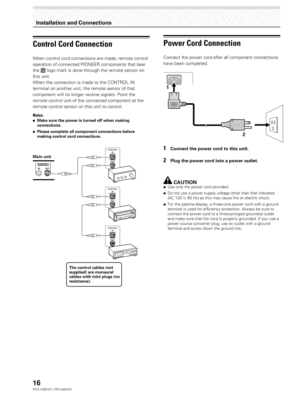
When control cord connections are made, remote control operation of connected PIONEER components that bear the Î logo mark is done through the remote sensor on this unit.
When the connection is made to the CONTROL IN terminal on another unit, the remote sensor of that component will no longer receive signals. Point the remote control unit of the connected component at the remote control sensor on this unit to control.
Notes
÷Make sure the power is turned off when making connections.
÷Please complete all component connections before making control cord connections.
CONTROL
IN
Main unit
OUT
CONTROL
IN OUT
CONTROL
IN
OUT
CONTROL
IN
OUT
The control cables (not supplied) are monaural cables with mini plugs (no resistance).
Power Cord Connection
Connect the power cord after all component connections have been completed.
1
2
1Connect the power cord to this unit.
2Plug the power cord into a power outlet.
![]() CAUTION
CAUTION
÷Use only the power cord provided.
÷Do not use a power supply voltage other than that indicated (AC 120 V, 60 Hz) as this may cause fire or electric shock.
÷For the plasma display, a
16
