Other connections | 08 |
Using the i.LINK interface
VSX-74TXVi only
If you have a component with an i.LINK connector, you can connect it to this receiver using an i.LINK cable.
Since the i.LINK interface does not transmit video signals, the video signal of
The two i.LINK connectors on the rear of your receiver are
![]() Caution
Caution
•If your i.LINK connector comes into contact with metallic parts of the receiver other than the i.LINK terminal, an electrical short may occur. Some cables have metal parts that may touch the unit when connected. Please take care to use a suitable i.LINK cable only.
![]() Important
Important
•Please use
•There may be cases where the PQLS/rate control function and/or the i.LINK audio does not work prop- erly even when connected to i.LINK
•Do not connect/disconnect i.LINK cables or switch on/off any components connected using i.LINK when the receiver is on.
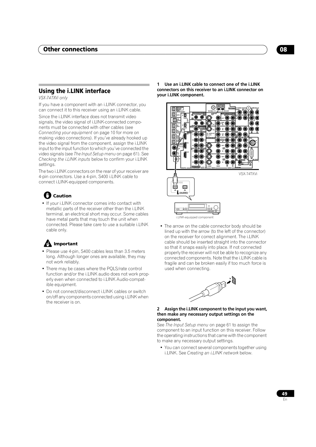
1Use an i.LINK cable to connect one of the i.LINK connectors on this receiver to an i.LINK connector on your i.LINK component.
|
|
|
|
|
|
|
| ANTENNA | AUDIO |
|
| PRE OUT |
| ||||
&SOURCE |
|
|
|
|
|
|
|
|
|
|
| ||||||
/REC SEL |
|
|
|
|
|
|
|
|
|
| PHONO |
|
| R | L | F | |
OUT1 |
|
|
|
|
|
| FM UNBAL 75Ω |
| AM LOOP |
|
|
|
|
|
|
|
|
ROOM3(ZONE3) |
|
|
|
|
|
| IN |
|
|
|
|
|
| ||||
|
|
|
| MONITOR |
|
|
|
|
|
| |||||||
OUT2 |
|
| IN | ROOM2(ZONE2) OUT | OUT |
| R ROOM2(ZONE2) L | CD |
|
|
| SUBW. |
| C | |||
USB | S400 |
| IR |
|
|
|
| OUT |
| IN |
|
|
|
|
|
| |
|
|
|
|
|
|
|
|
|
|
|
|
|
|
|
|
| |
AUDIO |
|
|
|
| 12 V TRIGGER |
|
|
|
|
|
|
|
|
|
|
|
|
IN | (AUDIO) |
|
|
|
|
|
|
| DVD/ |
|
|
|
|
|
|
|
|
|
|
| 1 | 2 |
|
|
|
|
|
|
|
|
|
| |||
|
|
|
| IN1 |
| LD |
|
|
|
|
|
|
|
| |||
IN1 |
|
| (DC OUT 12VTOTAL 50mA MAX) |
| IN |
|
|
|
|
|
|
|
| ||||
(SAT) | S400 | ROOM2 |
|
|
|
| OUT |
|
|
|
|
|
| ||||
|
|
|
| & SOURCE |
|
| TV |
|
|
|
|
|
|
|
| ||
IN2 |
| (ZONE2) | MONITOR | IN2 |
| IN |
|
|
|
|
|
|
|
| |||
| OUT |
|
|
|
|
|
|
|
|
|
|
| |||||
(DVR/ |
|
|
|
|
|
|
|
|
|
|
|
|
| R | L |
| |
VCR | HDMI | IN1 | OUT | IN1(DVD/LD) |
| SAT |
| TAPE |
|
|
|
| |||||
| IN1 |
| Y | Y | IN2(TV) |
|
| IN |
|
|
|
|
|
| |||
IN3 |
|
|
|
|
|
|
| IN |
|
|
|
|
|
|
| ||
|
|
|
|
|
|
|
|
| R |
|
| L |
|
|
| ||
VCR |
|
|
|
|
|
| ASSIGNABLE |
| VIDEO1/ |
| FR |
| FL |
| iPod |
|
|
IN4 |
|
| PB | PB |
|
|
|
|
|
|
|
|
|
| |||
|
|
|
| GAME1 |
|
|
|
|
|
| IN |
| |||||
|
|
|
|
|
|
|
| IN |
|
|
|
|
|
|
|
| |
IN2 |
|
|
|
|
|
|
|
|
| SUB W. | CENTER |
|
|
| |||
ASSIGNA- |
|
|
|
|
|
|
|
|
|
|
|
|
|
|
|
|
|
BLE |
|
| PR | PR |
|
| OUT |
|
|
|
|
|
|
|
| ||
IN1 |
|
|
|
|
|
|
|
| DVR/ |
| SUR- |
|
|
|
|
|
|
(DVD/ |
|
| IN | 2 | IN | 3 |
|
| VCR 1 |
| ROUND |
|
|
|
|
| |
LD) |
|
|
|
|
|
| IN |
|
|
|
|
|
|
|
| ||
| OUT |
| Y | Y |
|
|
|
|
|
|
|
|
|
| |||
IN2 |
|
|
|
|
|
|
|
|
|
|
|
|
|
|
|
| |
(CD) |
|
|
|
|
|
|
|
|
|
| R |
|
| L |
|
|
|
|
|
| PB | PB |
|
| OUT |
|
|
|
|
|
|
|
| ||
IN |
|
|
|
|
|
|
|
| DVR/ |
| R | SURROUND | L |
| |||
|
|
|
|
|
|
|
|
| VCR 2 |
|
|
|
| ||||
|
|
|
|
|
|
|
|
|
|
|
|
| BACK |
|
|
|
|
XM |
|
| PR | PR |
|
| IN |
|
|
| MULTI CH |
|
|
| |||
|
|
|
|
|
|
|
|
|
|
|
|
|
|
| |||
|
|
|
|
|
|
| S | VIDEO | R | L |
| OUT | IN |
| IN |
|
|
|
|
| ASSIGNABLE |
| CONTROL |
|
|
|
|
| |||||||
DIGITAL |
| COMPONENT VIDEO |
| VIDEO |
| AUDIO |
|
|
|
|
|
| |||||
|
|
|
|
|
|
|
|
|
|
| |||||||
|
|
|
|
|
|
|
|
|
|
|
|
|
| ||||
S400 |
|
|
|
|
|
|
|
|
|
|
|
|
|
|
|
|
|
(AUDIO) |
|
|
|
|
|
|
|
|
|
|
|
|
|
|
|
| |
•The arrow on the cable connector body should be lined up with the arrow (to the left of the connector) on the receiver for correct alignment. The i.LINK cable should be inserted straight into the connector so that it snaps easily into place. If not connected properly the receiver will not be able to recognize any connected components. Note that the i.LINK cable is fragile and can be broken easily if too much force is used when connecting.
2Assign the i.LINK component to the input you want, then make any necessary output settings on the component.
See The Input Setup menu on page 61 to assign the component to an input function on this receiver. Follow the operating instructions that came with the component to make any necessary output settings.
•You can connect several components together using i.LINK. See Creating an i.LINK network below.
49
En