Operating Instructions
For Australia Model
Operating Environment
Voltage selector
Changing the TV format setting
Changing the frequency step
10k
Contents
Using other functions
Other Settings
Other connections
Hdmi Control
Before you start
Installing the receiver
Before you start Chapter
Checking what’s in the box
Minute guide Chapter
Minute guide
Introduction to home theater
Listening to Surround Sound
Switch on the receiver and your TV
Speaker configuration in the OSD
Progress report is displayed on-screen while
Receiver outputs test tones to determine the speakers
Minute guide
Problems when using the Auto Mcacc Setup
Playing a source
Select the input source you want to play
Press Phase Phase Control to select Phase Control
Using Phase Control
Phase Control indicator on the front panel lights
02 5 minute guide
Press Phase Phase Control to select
Using Full Band Phase Control
Fullband PHASE.3
Tweeter Midrange Woofer
Connecting your equipment
Connecting your equipment Chapter
Rear panel
Connecting your equipment
When making cable connections
About the video converter
Connect using a standard video cable or an S-video cable
Connecting your equipment Connecting your TV and DVD player
Use an optical cable for the connection
Connecting a satellite/cable receiver or other set-top box
For a second recorder, use the DVR/VCR2 in inputs
Connecting a DVD/HDD recorder, VCR
About the WMA9 Pro decoder
Connecting digital audio sources
Use a three-way component video cable
This unit has an on-board Windows Media Audio
TV game, video camera, etc
Connecting your equipment Connecting analog audio sources
Connecting your equipment Installing your speaker system
Connecting the speakers
Center
Placing the speakers
Bare wire connections
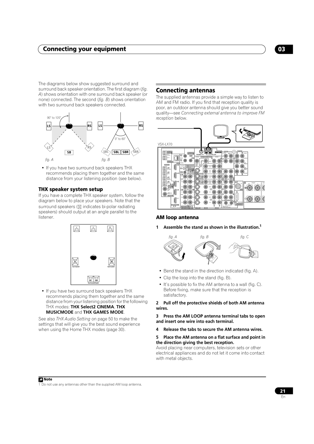
THX speaker system setup
Connecting antennas
AM loop antenna
Assemble the stand as shown in the illustration.1
Connecting external antenna to improve FM reception
FM wire antenna
Using the antenna adapter
Antenna Adapter
AC power cord and converter plug use
Using an external antenna to improve AM reception
Plugging in the receiver
Region Plug type
Controls and displays Chapter
Controls and displays
Front panel
STANDBY/ON
Controls and displays
Operating range of remote control unit
Controls and displays Display
Receiver
Controls and displays Remote control
Input Select
6TUNE/ST /ENTER
Multi OPE
Status
Shift
Source
Listening to your system Chapter
Listening to your system
Auto playback
Listening in surround sound
Using the Advanced surround effects
Using the Home THX modes
THX Games Mode
Listening to your system
Using Stream Direct
Using Front Stage Surround Advance
Listening in stereo
Tip
Choosing the input signal
Listening to your system Selecting Mcacc presets
Using surround back channel processing
While listening to a source, press Mcacc Mcacc Position
Using the Virtual Surround Back mode
BD Tvctrl
Using the tuner
Using the tuner Chapter
Listening to the radio
Naming station presets
Using the tuner Saving station presets
Listening to station presets
Abcdefghijklmnopqrstuvwxyz
System Setup menu Chapter
System Setup menu
Making receiver settings from the System Setup menu
Select the setting you want to adjust
Make sure ‘Normal default’ is selected,2 select an
System Setup menu
Point
Front Align
If necessary, confirm the speaker configuration in the OSD.1
Manual Mcacc setup
Surround back speaker setting
Select ‘Surr Back System’ from the System Setup menu
Select the surround back speaker setting
Select ‘Fine Ch Level’ from the Manual Mcacc setup menu
Select ‘Manual MCACC’ from the System Setup menu
Adjust the level of the left channel
When you’re finished, press Return
Select ‘Standing Wave’ from the Manual Mcacc setup menu
Select ‘Fine SP Distance’ from the Manual Mcacc setup menu
Fine Speaker Distance
Standing Wave
How to use Acoustic Calibration EQ Professional
Acoustic Calibration EQ Adjust
How to interpret the graphical output
Acoustic Calibration EQ Professional
Using Acoustic Calibration EQ Professional
Select ‘EQ Professional’ then press Enter
Select an option and press Enter
Full Band Phase Control
Select ‘FULL Band Phase CTRL’ from the System Setup menu
Checking Mcacc preset data
Select ‘Data Management’ from the System Setup menu
Data Management
Copying Mcacc preset data
Renaming Mcacc presets
Clearing Mcacc presets
Speaker Setting
System Setup menu Manual speaker setup
Select ‘Manual SP Setup’ then press Enter
Select ‘Speaker Setting’ from the Manual SP Setup menu
Speaker Distance
Channel Level
Curve
THX Audio Setting
Connecting your iPod to the receiver
Connecting an iPod
Other connections
Other connections Chapter
Watching photos and video content
Connecting using Hdmi
Other connections
Basic playback controls
About Hdmi
Selecting the multichannel analog inputs
Switching the speaker system
Use the Input Select button to select Multi CH
Select ‘Speaker B’ from the ‘Surr Back System’ menu
Bi-wiring your speakers
Bi-amping your front speakers
Connect your speakers as shown below
MULTI-ZONE listening
Other connections Connecting additional amplifiers
Making MULTI-ZONE connections
Sub zone Zone
Secondary MULTI-ZONE setup Zone
Basic MULTI-ZONE setup Zone
MULTI-ZONE listening options
Sub Zone Input sources available
Connecting an IR receiver
Using the MULTI-ZONE controls
MULTI-ZONE remote controls
Using this receiver with a Pioneer plasma display
Switching components on and off using the 12 volt trigger
Closet or shelving unit Non-Pioneer IRcomponent
Pioneer plasma
Using the SR+ mode with a Pioneer plasma display
Display
Satellite receiver, etc
Advanced Mcacc output using your PC
Other connections Connecting a PC for Advanced Mcacc output
When the receiver is ready for transmission, Start
Select ‘Output PC’ and press Enter
Hdmi Control
Hdmi Control Chapter
Making the Hdmi Control connections
Synchronized amp mode
Hdmi Control Setting the Hdmi options
Before using synchronization
About Hdmi Control
Other Settings
Other Settings Chapter
Input Setup menu
Other Setup menu
Input Input Terminals Source Digital
Video
Multi Channel Input Setup
Other Settings
Zone Audio Setup
SR+ Setup for Pioneer plasma displays
OSD Adjustment
Select the ‘PDP Volume Control’ setting you want
Select ‘OSD Adjustment’ from the Other Setup menu
Using other functions Chapter
Using other functions
Setting the Audio options
Setting What it does Options
Using other functions
Setting the Video options
Press V Parameter Video Parameter Use
Making an audio or a video recording
Playing a different source when recording
Select the source you want to record
Prepare the source you want to record
Switching the speaker impedance
Reducing the level of an analog signal
Using the sleep timer
Dimming the display
Resetting the system
Using other functions Checking your system settings
Default system settings
Setting Default
Listening Mode x ch
Neo6 Options Center Image All Inputs Listening Mode 2 ch
Listening Mode HP
Channel level M1-M6 Speaker Distance M1-M6
Setting the remote to control other components
Controlling the rest of your system
Controlling the rest of your system Chapter
Resetting the remote control presets
Erasing one of the remote control button settings
Confirming preset codes
Controlling the rest of your system
Multi Operation and System Off
Renaming input source names
Direct function
Programming a multi-operation or a shutdown sequence
Using multi operations
Using System off
Controls for TVs
Controls for other components
Buttons Function Components
Function Components
Decide which component you want to use the remote sensor
Operating other Pioneer components with this unit’s sensor
Disp SHIFT+
HDD
Power
Troubleshooting
Additional information
Additional information Chapter
Additional information
Other audio problems
Video
Phase Control feature
Settings
Professional Calibration EQ graphical output
Display
Remote control
IPod messages
Symptom Cause Action
Dolby
Additional information Surround sound formats
Windows Media Audio 9 Professional
About THX
About Neural Surround
Stereo 2 channel signal formats
Input signal format Standard
Auto Surround
Multichannel signal formats
Movie a MOVIE+THX a
THX Games Mode a
Pro Logic llx Movie a Pro Logic llx MOVIE+THX a
Movie a
Sacd Direct VSX-LX70 or Straight decoding VSX-LX60
Input signal format
Additional information Specifications
Additional information Cleaning the unit
Features
Our philosophy
Pioneer Authorized Distributors
DCDi
IPod Ready
Pioneer Corporation