N e t w o r k Tr a n s i e n t P r o t e c t o r
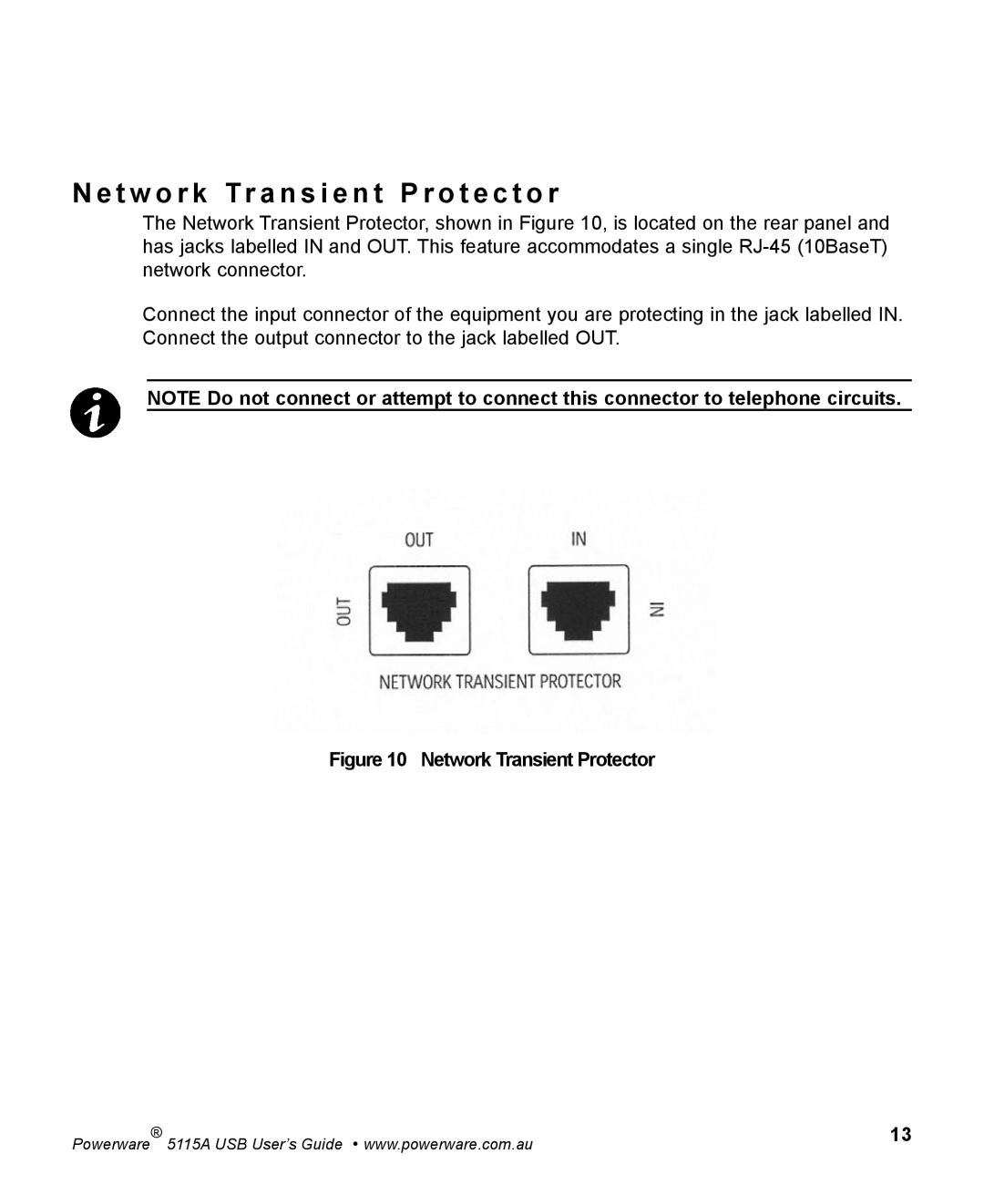
The Network Transient Protector, shown in Figure 10, is located on the rear panel and has jacks labelled IN and OUT. This feature accommodates a single
Connect the input connector of the equipment you are protecting in the jack labelled IN. Connect the output connector to the jack labelled OUT.
NOTE Do not connect or attempt to connect this connector to telephone circuits.
Figure 10 Network Transient Protector
Powerware | ® | 5115A USB User’s Guide • www.powerware.com.au | 13 |
|
|