manual
3.2 The Toolbox
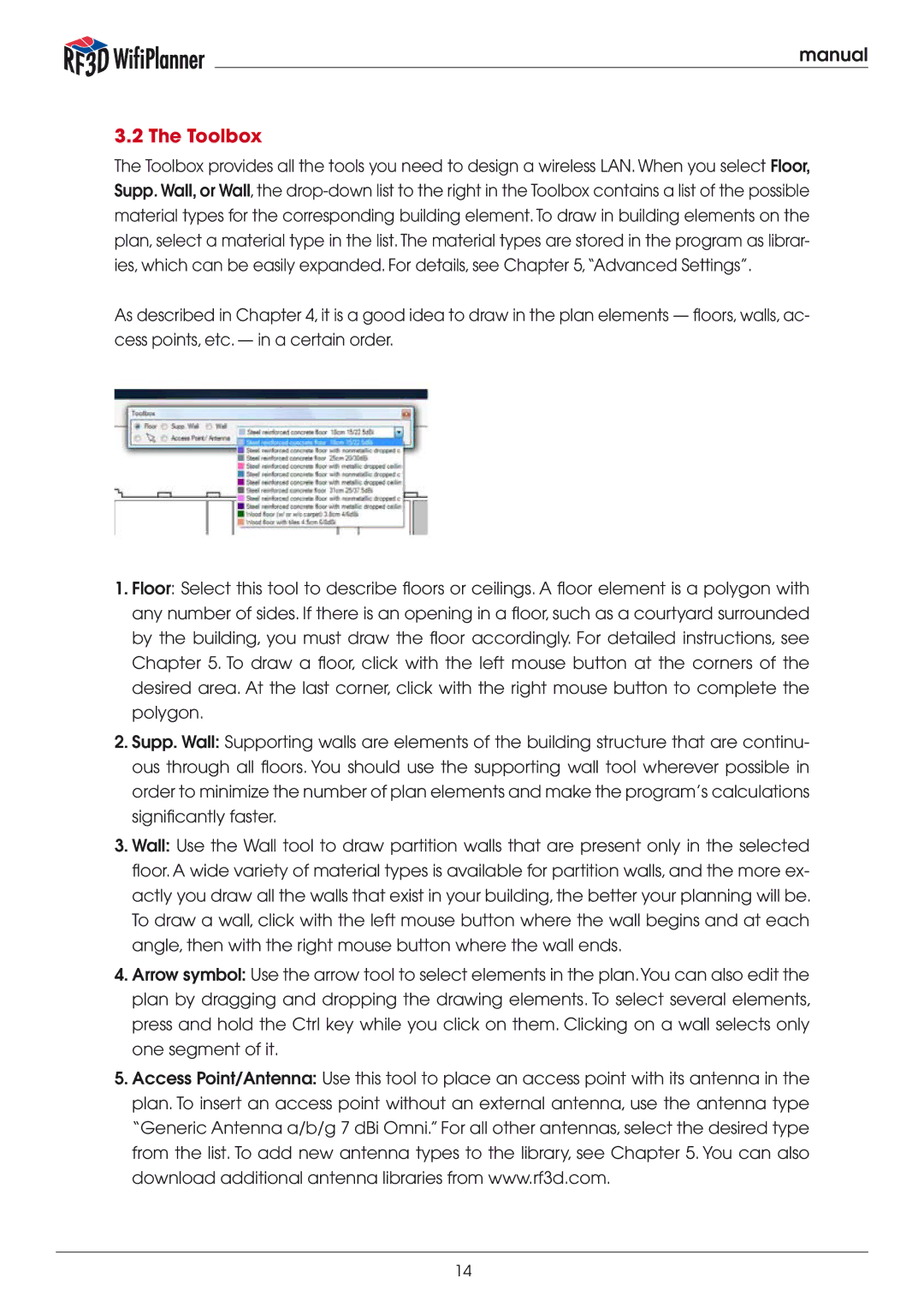
The Toolbox provides all the tools you need to design a wireless LAN. When you select Floor, Supp. Wall, or Wall, the
As described in Chapter 4, it is a good idea to draw in the plan elements — floors, walls, ac- cess points, etc. — in a certain order.
1.Floor: Select this tool to describe floors or ceilings. A floor element is a polygon with any number of sides. If there is an opening in a floor, such as a courtyard surrounded by the building, you must draw the floor accordingly. For detailed instructions, see Chapter 5. To draw a floor, click with the left mouse button at the corners of the desired area. At the last corner, click with the right mouse button to complete the polygon.
2.Supp. Wall: Supporting walls are elements of the building structure that are continu- ous through all floors. You should use the supporting wall tool wherever possible in order to minimize the number of plan elements and make the program’s calculations significantly faster.
3.Wall: Use the Wall tool to draw partition walls that are present only in the selected floor. A wide variety of material types is available for partition walls, and the more ex- actly you draw all the walls that exist in your building, the better your planning will be. To draw a wall, click with the left mouse button where the wall begins and at each angle, then with the right mouse button where the wall ends.
4.Arrow symbol: Use the arrow tool to select elements in the plan.You can also edit the plan by dragging and dropping the drawing elements. To select several elements, press and hold the Ctrl key while you click on them. Clicking on a wall selects only one segment of it.
5.Access Point/Antenna: Use this tool to place an access point with its antenna in the plan. To insert an access point without an external antenna, use the antenna type “Generic Antenna a/b/g 7 dBi Omni.” For all other antennas, select the desired type from the list. To add new antenna types to the library, see Chapter 5. You can also download additional antenna libraries from www.rf3d.com.
14