manual
3.3 Drawing and Selecting Elements
First select the desired element in the Toolbox, then choose the appropriate type of material.Draw in plan elements using both the left and right mouse buttons: first use the left mouse button to mark corners, then the right mouse button to finish the element.
Walls, floors and supporting walls are ordinarily drawn only in horizontal and vertical segments. But you can also draw diagonal segments at any angle simply by pressing the Ctrl key as you move the mouse. In this way you can draw walls and floors of any shape desired.
You can also select several walls at once, copy them to the Clipboard, and duplicate them in a different floor. Press and hold the Ctrl key while you select the desired ele- ments by clicking on them with the left mouse button. Then select the menu com- mand Edit/Copy (or press Ctrl+C). Choose the desired floor among the thumbnails in the left panel, then select the menu command Edit/Paste (or press Ctrl+V). If you make a mistake in editing the plan, use the menu command Edit/Undo (Ctrl+Z) to reverse the operation. To restore what you have undone, select Edit/Redo (Ctrl+Y).
3.4 The Simulation Tab
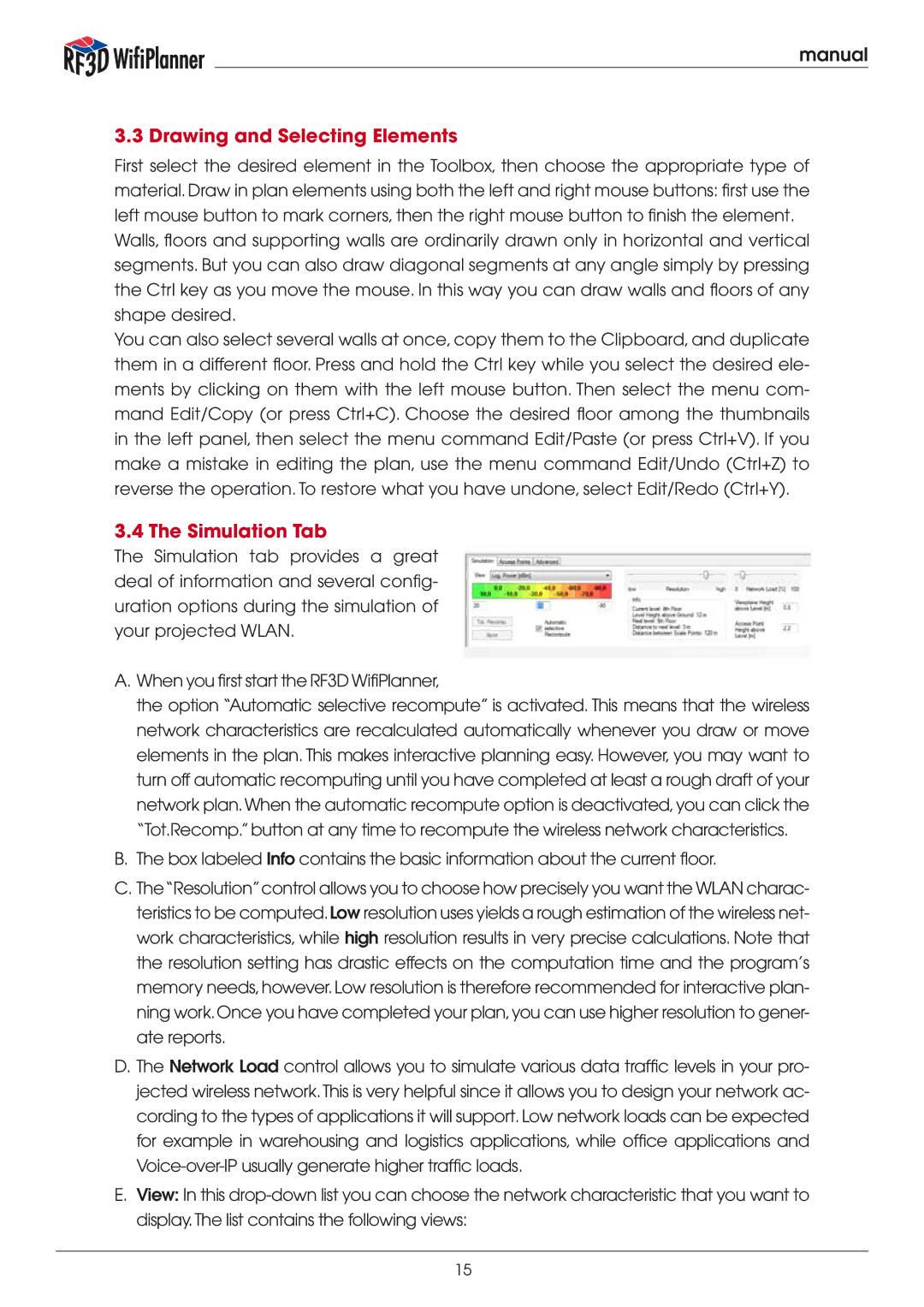
The Simulation tab provides a great deal of information and several config- uration options during the simulation of your projected WLAN.
A.When you first start the RF3D WifiPlanner,
the option “Automatic selective recompute” is activated. This means that the wireless network characteristics are recalculated automatically whenever you draw or move elements in the plan. This makes interactive planning easy. However, you may want to turn off automatic recomputing until you have completed at least a rough draft of your network plan. When the automatic recompute option is deactivated, you can click the “Tot.Recomp.” button at any time to recompute the wireless network characteristics.
B.The box labeled Info contains the basic information about the current floor.
C.The“Resolution” control allows you to choose how precisely you want the WLAN charac- teristics to be computed. Low resolution uses yields a rough estimation of the wireless net- work characteristics, while high resolution results in very precise calculations. Note that the resolution setting has drastic effects on the computation time and the program’s memory needs, however. Low resolution is therefore recommended for interactive plan- ning work. Once you have completed your plan, you can use higher resolution to gener- ate reports.
D.The Network Load control allows you to simulate various data traffic levels in your pro- jected wireless network. This is very helpful since it allows you to design your network ac- cording to the types of applications it will support. Low network loads can be expected for example in warehousing and logistics applications, while office applications and
E.View: In this
15