SANbox2-8c Fibre Channel Switch Installation Guide
Document Revision History
SANbox2-8c Fibre Channel Switch Installation Guide
Table of Contents
Distance Bandwidth Latency
Soft Zones Access Control List Hard Zones
User Account Security Fabric Services
Section Planning
Section Diagnostics/Troubleshooting
Section Installation
Appendix B Command Line Interface
Appendix a Specifications
Glossary Index
Tables
Figures
Related Materials
Intended Audience
New in this Release
Safety Notices Sicherheitshinweise
Federal Communications Commission FCC Class a Statement
Communications Statements
CE Statement
Bsmi Class a Statement
Vcci Class a Statement
Electrostatic Discharge Sensitivity Esds Precautions
Laser Safety Information
Accessible Parts
Pièces Accessibles
Zugängliche Teile
Preamble
General Public License
Introduction General Public License
Introduction
Introduction General Public License
Introduction
No Warranty
How to Apply These Terms to Your New Programs
Later version
ANY Warranty without even the implied warranty
Starts in an interactive mode
Hypothetical commands `show w and `show c should show
Contact Information
Technical Support
Availability
Training
General Description
Maintenance Button
Resetting a Switch
Chassis Controls and LEDs
Placing the Switch in Maintenance Mode
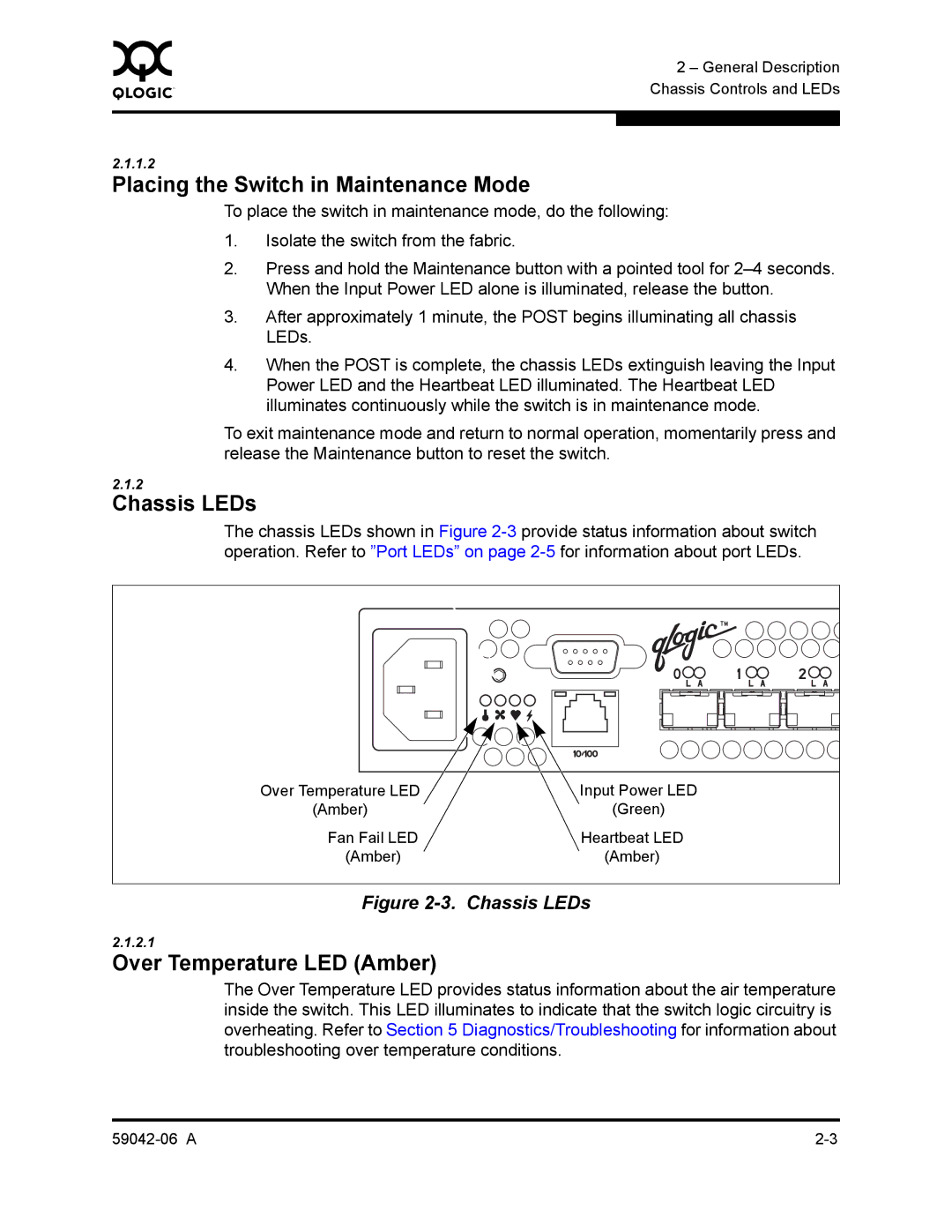
Over Temperature LED Amber
Chassis LEDs
Fibre Channel Ports
Input Power LED Green
Fan Fail LED Amber
Heartbeat LED Amber
Port LEDs
Port Logged-In LED
Port Activity LED
Port Types
Small Form-Factor Pluggable SFP Transceivers
Ethernet Port
Ethernet Port
Serial Port Pin Identification
Serial Port
Power Supply and Fan
Switch Management
SANsurfer Switch Manager
Simple Network Management Protocol
SANsurfer Switch Manager Web Applet
Command Line Interface
SANsurfer Switch Manager Application Programming Interface
File Transfer Protocol
General Description Switch Management 59042-06 a
Devices
Planning
Zoning Database Limits
Device Access
Soft Zones
Access Control List Hard Zones
Distance
Performance
Port-to-Port Latency
Bandwidth
Latency
Port-to-Port Transmission Combinations
Optimizing Device Performance
Multiple Chassis Fabrics
Domain ID, Principal Priority, and Domain ID Lock
Cascade Topology
Common Topologies
Mesh Topology
Mesh Topology
Multistage Topology
Multistage Topology
Fabric Services
Fabric Security
User Account Security
Fabric Management
Management Workstation Requirements
Switch Power Requirements
Site Requirements
Fabric Management Workstation
Environmental Conditions
Installing a Switch
Avertissement
Mount the Switch
Install SFP Transceivers
Ethernet and Serial Cable Connections
Connect the Workstation to the Switch
Choose Make New Connection
Configure the Workstation
Setting the Workstation IP Address for Ethernet Connections
Configuring the Workstation Serial Port
Data Bits
Enter the following COM Port settings in the COM Properties
Window and choose the OK button
‰ Bits per second
SANsurfer Management Suite Disk Windows Installation
Install SANsurfer Switch Manager
SANsurfer Management Suite Disk Linux Installation
SANsurfer Management Suite Disk Solaris Installation
Execute the install program
Follow the installation instructions
5.4
‰ For Linux or Solaris enter the SANsurfer command
Start SANsurfer Switch Manager
Connect the Switch to AC Power
Avertissement
Installation
Configure the Switch
Select the connection you created earlier and choose the OK
Cable Devices to the Switch
Choose the Start button, select Programs, Accessories
HyperTerminal, and HyperTerminal
Install Firmware
Using SANsurfer Switch Manager to Install Firmware
Using the CLI to Install Firmware
To start an admin session, enter the following
Enter the following command to install the new firmware
Using FTP and the CLI to Install Firmware
Wait for the unpack to complete
Powering Down a Switch
Post Diagnostics
Diagnostics/Troubleshooting
System Error Blink Pattern
Heartbeat LED Blink Patterns
Internal Firmware Failure Blink Pattern
Configuration File System Error Blink Pattern
Close the FTP session. ftpquit
Telnet xxx.xxx.xxx.xxx or Telnet switchname
Logged-In LED Indications
Logging Error
EPort Isolation
Excessive Port Errors
Diagnostics/Troubleshooting
Over Temperature LED is Illuminated
Chassis Diagnostics
Fan Fail LED is Illuminated
Input Power LED Is Extinguished
Recovering a Switch
Maintenance Image Unpack
Maintenance Exit
Maintenance Remove Switch Config
Maintenance Reset Network Config
Maintenance Reset User Accounts to Default
Maintenance Copy Log Files
Maintenance Set Active Image
Maintenance Show Firmware Versions
Diagnostics/Troubleshooting Recovering a Switch 59042-06 a
Fabric Specifications
Maintainability
Electrical
Dimensions
Environmental
Cispr 22, Class a
Regulatory Certifications
Vcci Class a ITE
Bsmi Class a
Specifications Regulatory Certifications 59042-06 a
User Accounts
Logging On to a Switch
Modifying a Configuration
Working with Switch Configurations
Backing up and Restoring Switch Configurations
When you are done making changes to the switch
Shown
Ftp ipaddress
Table B-1. Command-Line Completion
Commands
Admin Session Commands
Table B-2. Commands Listed by Authority Level
Keywords
Admin Command
Authority
Syntax
Syntax alias
Alias Command
Members alias
Remove alias memberlist
Rename aliasold aliasnew
Edit configname
Config Command
Syntax config
Keywords activate configname
Save configname
Restore
Manager Archive function are not compatible with the Config
Restore command
# ftp symbolicname or ipaddress
Date Command
Syntax date
Keywords MMDDhhmmCCYY
Fallback
Fallback Command
Syntax
Hardreset Command
Authority None
Help Command
Keywords command
Syntax help command keyword
Authority None Syntax history
History Command
Hotreset
Hotreset Command
Fetch accountname ipaddress filesource filedestination
Image Command
Cleanup
Image
Lip Command
Syntax passwd accountname Keywords accountname
Passwd Command
Ping Command
Syntax ping ipaddress
Keywords ipaddress
Displays current system process information
Ps Command
Following is an example of the Ps command
Syntax Examples
Quit Command
Closes the Telnet session
Syntax quit, exit, or logout
Config configname
Reset Command
Table B-3. Switch Configuration Defaults
System
Zoning
Arbff
Table B-4. Port Configuration Defaults
Table B-6. Zoning Configuration Defaults
Table B-5. Port Threshold Alarm Configuration Defaults
Table B-7. Snmp Configuration Defaults
Table B-8. System Configuration Defaults
Syntax set
Set Command
Setup option
Switch state
Port option
Port portnumber
Set Config Command
Set config
Table B-9. Set Config Port Parameters
Command Line Interface Set Config Command
Table B-9. Set Config Port Parameters
Table B-10. Set Config Switch Parameters
Threshold
Table B-11. Set Config Threshold Parameters
Memory. Refer to FC-SW-2 Compliant on page B-37 .
Table B-12. Set Config Zoning Parameters
Arbff
Following is an example of the Set Config Threshold command
Following is an example of the Set Config Switch command
RisingTrigger Decimal value 200 FallingTrigger SampleWindow
This
Following is an example of the Set Config Zoning command
Clear
Set Log Command
Set log
Archive
Start
Level level
Port portlist
Save
Stop
Set Port Command
Command Line Interface Set Port Command
Snmp System
Set Setup Command
Set setup
Table B-13. Snmp Configuration Settings
Table B-14. System Configuration Settings
Table B-14. System Configuration Settings
SANbox2 admin # set setup snmp
Command Line Interface
SANbox2 admin # set setup system
Following is an example of the Set Setup System command
Broadcast
Show Command
Alarm option
Keywords about
Fdmi portwwn
Log option
Ns option
Pagebreak
Perf option
Table B-15. Show Port Parameters
Lipalpdalps
Post log
Steering domainid
Support
Table B-16. Switch Operational Parameters
Table B-16. Switch Operational Parameters
Topology
Users
Version
Following is an example of the Show Fdmi WWN command
Following is an example of the Show Fdmi command
Following is an example of the Show NS local domain command
Following is an example of the Show NS domainID command
Following is an example of the Show NS portID command
Collisions0 txqueuelen100
Following is an example of the Show Interface command
LIPF8F7
Following is an example of the Show Port command
Following is an example of the Show Topology command
Following is an example of the Show Switch command
Command Line Interface Show Command
Following is an example of the Show Version command
Show config
Show Config Command
Following is an example of the Show Config Threshold command
Following is an example of the Show Config Switch command
Following is an example of the Show Config Zoning command
Level
Show Log Command
Show log
Component
Port
Settings
Following is an example of the Show Log Level command
Options
Following is an example of the Show Log command
Following is an example of the Show Log Options command
Show Perf Command
Following is an example of the Show Perf Byte command
Show Setup Command
Show setup
Mfg
Following is an example of the Show Setup Snmp command
Following is an example of the Show Setup System command
Shutdown Command
Power from the switch
Shutdown
Status
Test Command
Test
Port portnumber testtype
„ To run an internal loopback test, enter the following
Loopback plug must be installed for this test to pass
Command Line Interface Test Command
Uptime Command
Examples The following is an example of the Uptime command
Authority None Syntax uptime
Delete accountname
User Command
Keywords accounts
Add
Following is an example of the User Add command
Following is an example of the User Edit command
Following is an example of the User Delete command
Following is an example of the User List command
Whoami Command
Following is an example of the Whoami command
Whoami
Syntax zone
Zone Command
Type zone zonetype
Members zone
Remove zone memberlist
Rename zoneold zonenew
Following is an example of the Zone Members command
Following is an example of the Zone Zonesets command
Syntax zoneset
Zoneset Command
Remove zoneset zonelist
Rename zonesetold zonesetnew
Zones zoneset
History
Zoning Command
Keywords active
Opens a Zoning Edit session
Table B-17. Zoning Database Limits
Limits
E2JBOD2
Following is an example of the Zoning Limits command
Following is an example of the Zoning List command
100 59042-06 a
BootP
Access Control List Zone
Administrative State
Alarm
Fabric Management Switch
Class 3 Service
Configured Zone Sets
Default Visibility
Maintenance Mode
Input Power LED
Inter-Switch Link
Maintenance Button
SANsurfer Switch Manager
Over Temperature LED
Power On Self Test Post
Principal Switch
Set of zone sets, zones, and aliases stored on a switch
Zone Set
Zoning Database
Page
Numerics
Index
Index-2 59042-06 a
LED
Index-4 59042-06 a
59042-06 a Index-5
Start
Database 3-2,B-26