Chapter 2 Installation
Installing an Internal
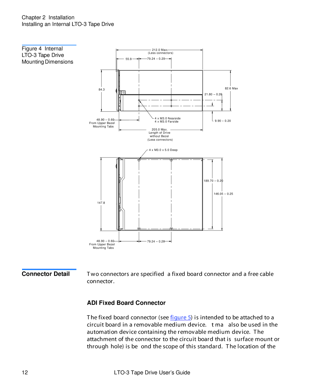
Figure 4 Internal
LTO-3 Tape Drive
Mounting Dimensions
84.3
212.0 Max. (Less connectors)
55.9 ![]() 79.24 ± 0.20
79.24 ± 0.20
82.6 Max
21.80 ± 0.20
48.90 ± 0.60 |
| 4 x M3.0 Nearside |
From Upper Bezel |
| 4 x M3.0 Farside |
|
| |
Mounting Tabs |
|
|
205.0 Max.
Length of Drive
without Bezel
(Less connectors)
9.90 ± 0.20
147.8
48.90± 0.60 From Upper Bezel Mounting Tabs
4 x M3.0 x 5.0 Deep
189.70 ± 0.20
146.05 ± 0.25
79.24 ± 0.20
Connector Detail Two connectors are specified, a fixed board connector and a free cable connector.
ADI Fixed Board Connector
The fixed board connector (see figure 5) is intended to be attached to a circuit board in a removable medium device. It may also be used in the automation device containing the removable medium device. The attachment of the connector to the circuit board that is, surface mount or
12 |
|