International Headquarters RAD Data Communications Inc
IPmux-1, IPmux-1E
Regulatory Information
Safety Status Ports
Safety Warnings
Manufacturer’s Address
Safety
Declares that the product Product Name IPmux-1
Supplementary Information
Contents
Application Configuration Procedures
Troubleshooting and Diagnostics
IPmux-4
IPmux-1 View
Packet Delay Variation
IPmux-1
Performance Monitoring Menu for IPmux-1
Default Gateway Menu
Authentication/Community Menu
Overview
Chapter Introduction
Versions
IPmux-1 with E1 interface
2shows an E1/T1 circuit extension over an IP based Network
Applications
E1/T1 Circuit Extension over an IP Based Network
E1 CAS
Extending BRI Ports of a Small Office
Interface Concentration
Management
Features
Ethernet User Port
IPmux-1E can be configured to 1, 2, 3 or 4 active ports
Ethernet Physical Port
Fiber option standard 100BaseF full duplex port see Table
Fiber Options
Mode of Operation
To calculate Optical Budget
To calculate Distance
Timing
QoS
Standards
Level 2 Priority
IPmux-1 3-D View
Physical Description
Front Panel
Functional Description
Rear Panel
IPmux-1 E1/T1
Operation Modes
Other BRI/FXS applications are shown in -3, -4, and Figure
IPmux-1E Isdn BRI
IPmux-1E FXS operates E1 mode T1-D4 mode T1 ESF mode
IPmux-1E FXS
BRI/FXS TS Assignment in a Bundle
Testing
First Channel Second Channel
E1/T1
Timing Modes
External Network Timing
Network Timing Schemes
Single Source Clock Network
Frame Format
14. IPmux-1 in Adaptive Timing Mode
Layer IP Layer
Layer
Layer Data
Vlan Support
UDP Support
Packet Delay Variation
UDP Ports Definition
Bundle 1 02, Bundle 2 03, Bundle 3 04, Bundle 4 05, etc
To configure jitter buffer depth
Pdvt Buffer Effect on Delay
Pdvt Jitter Buffer
Ethernet Throughput
Ethernet Throughput Unframed T1
Ethernet Throughput Unframed E1
End-to-End Alarm Generation
Round Trip Delay
Ethernet User Port
Internal Switch Operation Modes
Technical Specifications
Baud Rate
Mode
Ports
Range
External Clock
Interface
Power
Indicators
Technical Specifications
Introduction
Chapter Installation
Site Requirements and Prerequisites
Installation and Setup
Package Contents
Equipment Needed
To open the IPmux-1E case
IPmux-1E
To set the IPmux-1E ISDN-S module jumpers
IPmux-1E ISDN-S Jumpers
Connecting Interfaces and Cables
IPmux-1 Front Panel for Two Ethernet Ports
Grounding
Location of Connectors
Fuses
Ethernet Port Pinout
E1/T1 Port Connectors Pinout
Control Port Pinout
Pin Designation Direction Function
ISDN-S Interface Pin Assignments
Connecting the Control Port
FXS Interface Pin Assignments for RJ-11
AC Power Connection
Connecting the Power
DC Power Connection
To connect AC power to IPmux-1/1E
Installation Installation and Setup
Chapter Operation
Front Panel Controls, Connectors, and Indicators
Name Type Function
IPmux-1 Front Panel LEDs
IPmux-1E Front Panel Indicators
Turning IPmux-1/1E On
Operating Instructions
Without Control Terminal
With Control Terminal
User Name and Password
Login
Turning IPmux-1/1E Off
Overview of Menu Operations
Getting Started
Navigating
Main Menu
IPmux-1 E1/T1 Terminal Menu Tree
IPmux-1E ISDN-S Terminal Menu Tree
IPmux-1E FXS Terminal Menu Tree
System Menu
Main Menu
To access the Configuration menu
Setting IPmux-1/1E Configuration Options
E1/T1/ISDN/FXS Configuration
General Configuration
Bundle Connection Configuration
LAN Configuration
To view Performance Statistics
Performance Monitoring
From the Performance Monitoring menu you can view
E1/T1/ ISDN/ Analog Statistics
Operation Overview of Menu Operations
Error Detection
Chapter Troubleshooting Diagnostics
Using Front Panel LEDs
Working with the Alarm Buffer
Event Description Corrective Action
Event Types
Diagnostic Tests
Troubleshooting
IPmux-1 Troubleshooting Chart
E1/T1
To run a loopback test
Internal Loop
Tone Injection
Remote Loopback
To run a test
Troubleshooting and Diagnostics Diagnostic Tests
Application
Chapter Application Configuration Procedures
E1/T1 Configuration
IP Configuration
Guidelines
Creating Bundles and Connections
Bundle Configuration
Configuration Summary Table
Configuration Summary
E1 Channel Bundle Number for E1 Bundle Number for T1
IPmux-1
Powering-up
Changing Parameters
Checking Connectivity
Procedure for Modifying Parameters
Configuring IPmux-1 Station a
Host IP Address
To modify parameters
To configure E1/T1
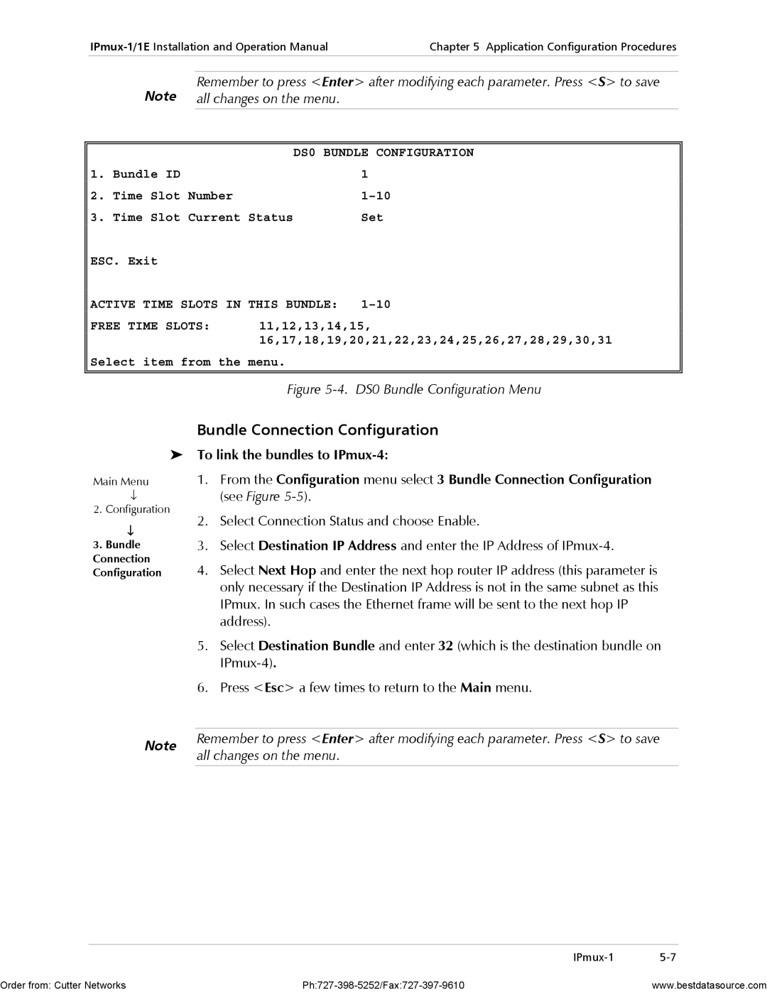
DS0 Bundle Configuration
From the Main menu, select 2 Configuration
E1/T1 Configuration
DS0 Bundle Configuration
Bundle Connection Configuration
All changes on the menu
Active Time Slots in this Bundle Free Time Slots
Power-up in the same manner as for IPmux-1 Station a
Configuring IPmux-1 Station B
To configure the Host IP Address
From the Configuration menu select 1 General Configuration
To link the bundles to IPmux-4
To create the bundles
Press Esc to return to the Main screen
IPmux-4
To turn on IPmux-4
To configure Host IP Address
Configuration
From the General Configuration menu, press
From the DS0 Bundle Configuration menu, press
To configure DS0 Bundles for Station a
To configure DS0 Bundles for Station B
Physical Layer Configuration
For TDM Bytes, 3 ms for Jitter Buffer
Save all changes on the menu
Authentication/Community
Configuring the Management Option
To configure Authentication/Community
AUTHENTICATION/COMMUNITY Menu
To configure the Manager in IPmux-1/4
Manager List
IPmux-1/4
Default Gateway
Alarms Trap Mask
To configure the Alarms Trap Mask
To configure the Default Gateway
To check the application using IPmux Statistics
Using IPmux Statistics Step
Default Gateway
Checking the Application
Using TDM Equipment Statistics and Functionality Step
Booting IPmux-1/1E
Appendix a Boot Sequence for Downloading Software
Boot Sequence
General
To access the file system
Accessing the File System
Exist
Figure A-2. File System Menu
Order from Cutter Networks Ph727-398-5252/Fax727-397-9610
Appendix B Telnet
Using Telnet to Manage the IPmux-1/1E
Starting a Telnet Session
To open a Telnet application
System Security
Telnet Operation
To establish a Telnet session
Snmp Environment
Appendix C Snmp Management
Snmp Principles
Snmp Operations
MIB Structure
Management Information Base MIB
MIBs Supported by the IPmux-1/1E Snmp Agent
Snmp Communities
Management Domains under Snmp
IPmux-1E object id is
Network Management Stations
Authentication
Inband Tftp Download Procedure
Appendix D Tftp Download Procedures
To start download
Before performing Tftp download
Preliminary Procedure
Log in as Superuser su
To check the download
Checking the Download
Press Start Query
Figure D-3. System Description
Tftp
Appendix E Parameters and Screens
Main Menu
Configuration
System
Performance Monitoring
General Information
Viewing the IPmux-1/1E System
General Information
UTP
To reset the IPmux-1/1E configuration
Reset
Self-Test Results
For details
Ping
Logfile Events
Read Logfile
Logfile Events
Main Menu To configure the Host IP address and IP Mask
General Configuration
To change a configured Host IP
Set the device to the default settings
Authentication/Community
Default Gateway
Type 2 Default Gateway in the General Configuration menu
Enter the Default Gateway IP address
Manager List
To access additional manager-list parameters
Press N to go to the next Manager List window
Table E-5. IPmux-1/1E Alarms
Alarm Traps Mask
Alarm Traps Mask
Alarm ID Alarm Description Trap Sent to NMS
Other alarms are not used
Ascii Terminal Configuration
Ascii Terminal Configuration
Download/Upload Using Xmodem
Time/Date Update
To Download/Upload using Xmodem
TIME/DATE Update
Table E-9. Download/Upload Using Tftp Parameters
Table E-8. Download/Upload Using X-Modem Parameters
DOWNLOAD/UPLOAD Using Tftp
To save the parameters and start the transmission process
Set Default Parameters
View Transfer Status
E1 Configuration
IPmux-1 E1/T1 Configuration
Configuration
Default Gateway Configuration
Table E-11. E1 Physical Layer Configuration Parameters
CAS disable
CAS enable
To F
T1 Configuration
T1 Configuration
T1-ESF
B8ZS
T1-D4
Table E-12. T1 Configuration Parameters
DSU 0-133
267-399 534-655 CSU 0 dB, -7.5 dB 15 dB, -22.5 dB
Seconds
Isdn Configuration
IPmux-1E Isdn Configuration
Table E-13. Isdn Configuration
Isdn Channel Configuration
Isdn Channel Configuration
Table E-14. Isdn Channel Parameters
Analog Configuration
Analog Configuration
Channel Configuration
Channel Configuration
Signaling Profile Configuration
Signaling Profile Configuration
Table E-17. Signaling Profile Configuration
Bundle Connection Configuration
YES
288, 336
48, 96, 144, 192
To 300 milliseconds
Yes
Table E-19. LAN Configuration Parameters
LAN Configuration no User port
LAN Configuration
Default 100baseT Full Duplex
To save the change
DS0 Bundle Configuration
SET
Active Timeslots This Bundle
E1/T1 Statistics
Performance Monitoring
Compliance to Standards
Table E-21. E1/T1 Statistics Parameters
Alarm Failure Comments
SES
Table E-21. E1/T1 Statistics
Table E-22. Isdn Statistics Parameters
Isdn Statistics in IPmux-1
To view statistics for the next interval
Press N
LAN Statistics no User port
Analog Status IPmux-1E with FXS
Options for each channel are On-hook,Off-hook, Ringing
LAN statistics are not collected in intervals
Table E-23. LAN Statistics
To reset counters Type R
Bundle Connection Statistics
To reset counters
Type R
Table E-24. Bundle Connection Status Parameters
User port is present
Ethernet Configuration/Statistics Menus
Table E-24. Bundle Connection Statistics Parameters
Switch Configuration
LAN Configuration
Aging Time
Select Aging Time from 10 to 450 seconds
LAN Statistics
Table E-25. LAN Configuration Two Ethernet Ports
For further details, see Ethernet User Port in Chapter
Figure E-38. LAN Statistics Menu Two Ethernet Ports Internal
To view statistics for next channel
Frames received
Table E-26. LAN Statistics Two Ethernet Ports
Channel1 Network, User, Internal
B7ZS, E-18 B8ZS, E-18
Index
Isdn BRI
Index
QoS Rack
XMODEM, E-11
DC Power Supply Connection Terminal Block Connector