22 | ST60 Wind & Close Hauled Wind Instrument Owner’s Handbook |
5.Secure all sections together using the two fixing screws, but do not fully tighten at this stage.
6.Ensure the main shaft of the Rotavecta is vertical, then tighten the two fixing screws.
7.Screw in the grub screw, to pinch the rail.
Running transducer cable
General
Each transducer type is supplied with sufficient cable already connected, to run from the mounted position to the ST60 Wind instrument. The manner in which you run the cable will depend on the locations of the transducer and instrument.
Observing the following guidelines, run the transducer cable to the instrument:
•If the cable has to be fed through the deck, always use a proprietary deck gland.
•Where cables are fed through holes, always use grommets to prevent chafing.
•Secure long cable runs so they do not present a hazard.
•If the transducer is mounted on a masthead or other structure likely to be removed for maintenance or storage purposes (e.g. a mast), always incorpo- rate a junction box into the cable run as close as possible to the cable entry point into the vessel, to facilitate disconnection when required.
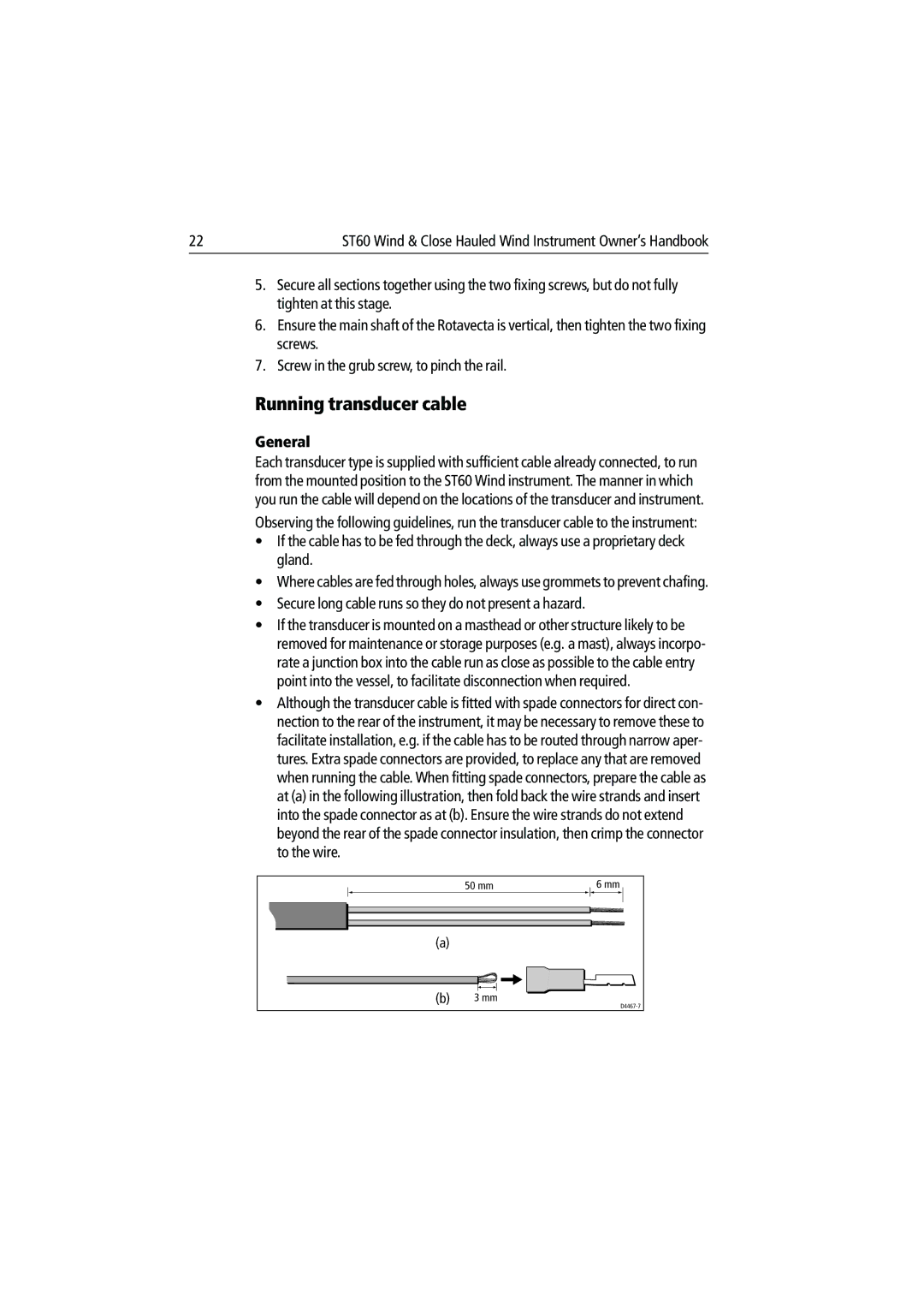
•Although the transducer cable is fitted with spade connectors for direct con- nection to the rear of the instrument, it may be necessary to remove these to facilitate installation, e.g. if the cable has to be routed through narrow aper- tures. Extra spade connectors are provided, to replace any that are removed when running the cable. When fitting spade connectors, prepare the cable as at (a) in the following illustration, then fold back the wire strands and insert into the spade connector as at (b). Ensure the wire strands do not extend beyond the rear of the spade connector insulation, then crimp the connector to the wire.
| 50 mm | 6 mm |
(a) |
|
|
(b) | 3 mm | |
|
|
