INTERNAL AUTOMATIC BYPASS VALVE |
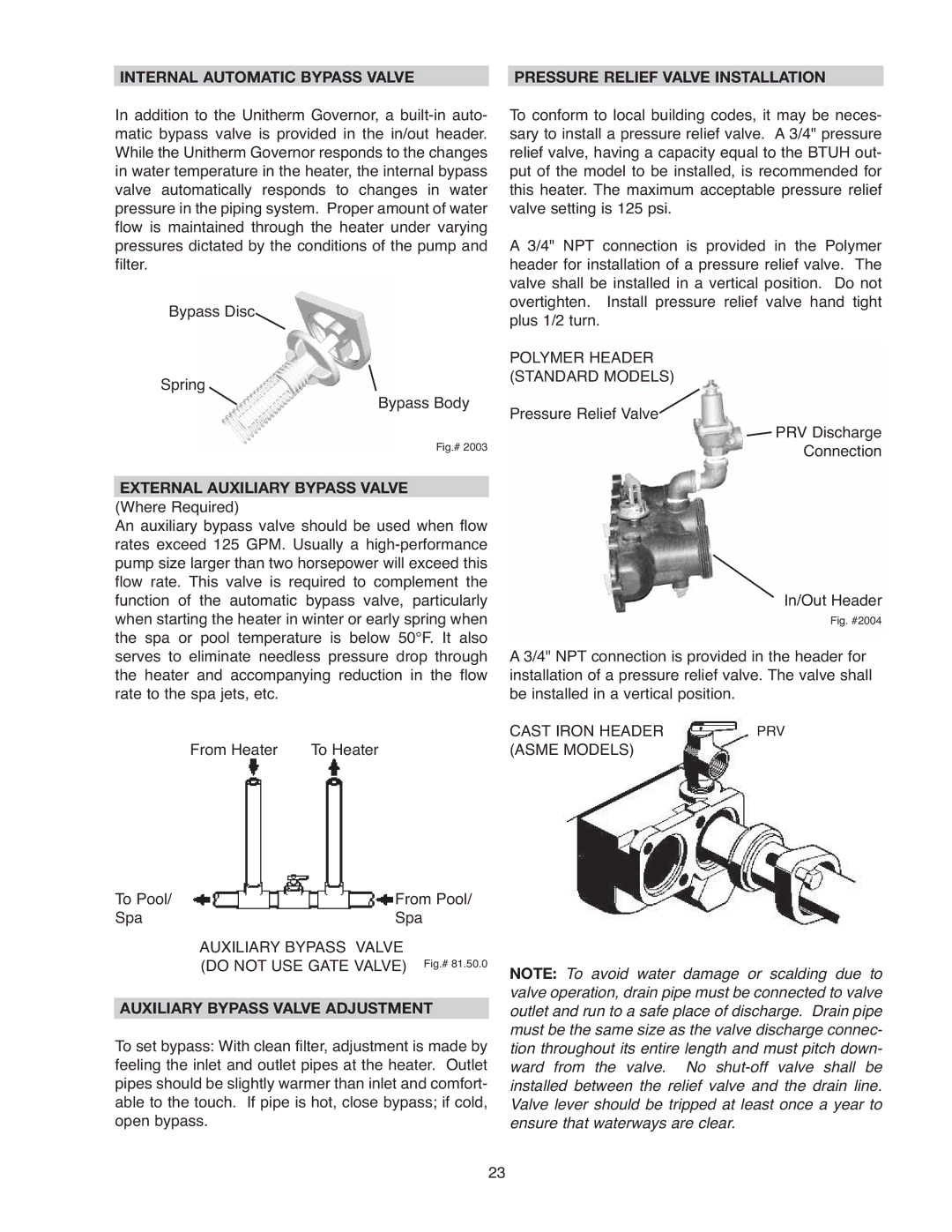
| PRESSURE RELIEF VALVE INSTALLATION |
In addition to the Unitherm Governor, a
Bypass Disc
Spring
Bypass Body
Fig.# 2003
EXTERNAL AUXILIARY BYPASS VALVE
(Where Required)
An auxiliary bypass valve should be used when flow rates exceed 125 GPM. Usually a
From Heater To Heater
To Pool/ | From Pool/ |
Spa | Spa |
| AUXILIARY BYPASS VALVE |
| (DO NOT USE GATE VALVE) Fig.# 81.50.0 |
AUXILIARY BYPASS VALVE ADJUSTMENT
To set bypass: With clean filter, adjustment is made by feeling the inlet and outlet pipes at the heater. Outlet pipes should be slightly warmer than inlet and comfort- able to the touch. If pipe is hot, close bypass; if cold, open bypass.
To conform to local building codes, it may be neces- sary to install a pressure relief valve. A 3/4" pressure relief valve, having a capacity equal to the BTUH out- put of the model to be installed, is recommended for this heater. The maximum acceptable pressure relief valve setting is 125 psi.
A 3/4" NPT connection is provided in the Polymer header for installation of a pressure relief valve. The valve shall be installed in a vertical position. Do not overtighten. Install pressure relief valve hand tight plus 1/2 turn.
POLYMER HEADER
(STANDARD MODELS)
Pressure Relief Valve![]()
![]() PRV Discharge
PRV Discharge
Connection
In/Out Header
Fig. #2004
A 3/4" NPT connection is provided in the header for installation of a pressure relief valve. The valve shall be installed in a vertical position.
CAST IRON HEADER | PRV |
(ASME MODELS) |
|
NOTE: To avoid water damage or scalding due to valve operation, drain pipe must be connected to valve outlet and run to a safe place of discharge. Drain pipe must be the same size as the valve discharge connec- tion throughout its entire length and must pitch down- ward from the valve. No
23