COMBUSTION AND VENTILATION AIR (Indoor Units Only)
The heater must have both combustion and ventilation air. Minimum requirements for net free air supply open- ings are one opening that is 12 inches from the ceiling for ventilation, and one opening that is 12 inches from the floor for combustion air as outlined in the latest edition of the National Fuel Gas Code, ANSI Z223.1(Canada-
A.All Air From Inside The Building:
Each opening shall have a minimum net free area as noted:
Model | Square Inches | Model | Square Inches |
|
|
|
|
206/207 | 200 | 336/337 | 333 |
|
|
|
|
266/267 | 266 | 406/407 | 399 |
|
|
|
|
B.All Air From Outdoors:
When air is supplied directly from outside of build- ing, each opening shall have a minimum net free area as noted:
Model | Square Inches |
|
|
206/207 | 50 |
|
|
266/267 | 67 |
|
|
336/337 | 84 |
|
|
406/407 | 100 |
|
|
CAUTION: Combustion air must not be contaminated by corrosive chemical fumes which can damage the heater and void the warranty.
VENT PIPING
WARNING: Indoor heaters require a drafthood that must be connected to a vent pipe and properly vented to the outside. Failure to follow this procedure can cause fire or fatal carbon monoxide poisoning.
Vent piping the same size as the drafthood outlet is recommended, however, when the total vent height is at least 10 ft (drafthood relief opening to vent terminal), the vent pipe size may be reduced as specified in Chapter 10 of the National Fuel Gas Code, ANSI Z223.1 (Canada -
Power Vent Kit
Model Part No.
206/207 009832
266/267 009832
336/337 009833
406/407 009833
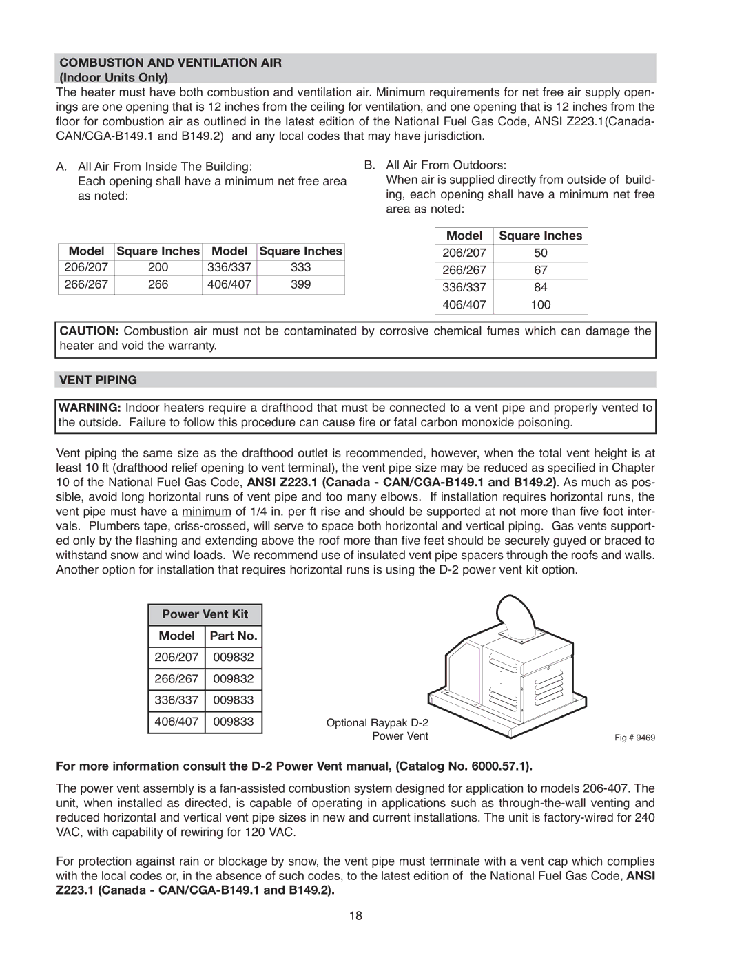
Optional Raypak |
|
Power Vent | Fig.# 9469 |
For more information consult the
The power vent assembly is a
For protection against rain or blockage by snow, the vent pipe must terminate with a vent cap which complies with the local codes or, in the absence of such codes, to the latest edition of the National Fuel Gas Code, ANSI
Z223.1 (Canada - CAN/CGA-B149.1 and B149.2).
18