INSTALLATION

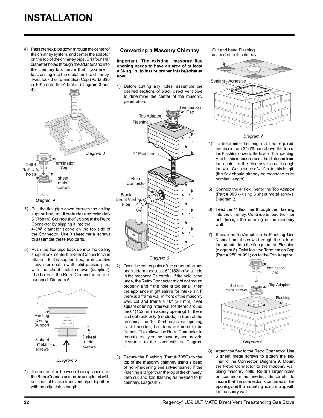
4)Pass the flex pipe down through the center of the chimney system, and center the adaptor on the top of the chimney pipe. Drill four 1/8"

diameter holes through the adaptor and into the chimney top. Insure that you are in fact, drilling into the metal on the chimney. Twist-lock the Termination Cap (Part# 980 or 991) onto the Adaptor. (Diagram 3 and 4).

Converting a Masonry Chimney

Important: The existing masonry flue opening needs to have an area of at least a 36 sq. in. to insure proper intake/exhaust flow.

1)Before cutting any holes, assemble the desired sections of black direct vent pipe to determine the center of the masonry penetration.

Diagram 3

Diagram 4

5)Pull the fl ex pipe down through the ceiling support box, until it protrudes approximately 3" (76mm).Connecttheflex pipe to theRetro Connector by slipping it into the

4-3/4" diameter sleeve on the top side of the Connector. Use 3 sheet metal screws to assemble these two parts.

6)Push the fl ex pipe back up into the ceiling supportbox,centertheRetroConnector,and attach it to the support box, or decorative sleeve for double wall solid packed pipe, with the sheet metal screws (supplied). The holes in the Retro Connector are pre- punched. Diagram 5.

Diagram 6

2)Once the center point of the penetration has been determined, cut a 6" (152mm) dia. hole in the masonry. Be careful, if the hole is too large, the Retro Connector might not mount properly, and if the hole is too small, then the appliance might starve for intake air. If there is a frame wall in front of the masonry wall, cut and frame a 10" (254mm) clear square opening in the wall (centered around the 6" (152mm) masonry opening). IF there is sheet rock only (no studs) in front of the masonry, the 10" (254mm) clear opening is still needed, but does not need to be framed. This allows the Retro Connector to mount directly on the masonry and provide clearance to the combustibles. Diagram 11.

Diagram 7

4)To determine the length of fl ex required, measure from 3" (76mm) above the top of theFlashingdowntotheleveloftheopening. Add to this measurement the distance from the center of the chimney to out through the wall. Cut a piece of 4" fl ex to this length (the fl ex should already be extended to its nominal length).

5)Connect the 4" fl ex liner to the Top Adaptor (Part # 985K) using 3 sheet metal screws. Diagram 2.

6)Feed the 4" fl ex liner through the Flashing into the chimney. Continue to feed the liner out through the opening in the masonry wall.

7)Secure the TopAdaptor to the Flashing. Use 3 sheet metal screws through the side of the adaptor into the fl ange on the Flashing (diagram 8). Twist lock the Termination Cap (Part # 980 or 991) on to the Top Adaptor.

Diagram 8

3)

Secure the Flashing (Part # 705C) to the

Diagram 5

top of the masonry chimney using a bead


7) The connection between the appliance and

of non-hardening sealant-adhesive. If the

Flashingislargerthanthetopofthechimney,

the Retro Connector may be completed with

then cut and fold fl ashing as needed to fi t

sections of black direct vent pipe, together

chimney. Diagram 7.

with an adjustable length.


8)Attach the fl ex to the Retro Connector. Use 3 sheet metal screws to attach the fl ex liner to the Connector. Diagram 9. Mount the Retro Connector to the masonry wall using masonry bolts. Re-drill larger holes on connector as needed. Be careful to insure that the connector is centered in the opening and the mounting holes line up with the masonry wall.

22

Regency® U39 ULTIMATE Direct Vent Freestanding Gas Stove

Page 22
Image 22
Regency U39-LP1, U39-NG1 installation manual Converting a Masonry Chimney

U39-LP1, U39-NG1 specifications

The Regency U39-LP1 and U39-NG1 are innovative heating appliances designed for modern homes, emphasizing both efficiency and style. These units encapsulate the essence of contemporary design while ensuring high-performance heating solutions. The U39 series stands out for its user-friendly features and advanced technologies that cater to the demands of varied environments.

One of the main features of the U39-LP1 is its propane-fueled operation, allowing it to generate an impressive amount of heat while remaining energy-efficient. The unit is designed with a remarkable heating capacity, making it ideal for larger spaces or for those chilly evenings where comfort is paramount. In contrast, the U39-NG1 operates on natural gas, appealing to homeowners looking for a more sustainable option. Both models allow for quick and effective heating, ensuring a cozy atmosphere within moments.

The technology embedded in both models reflects a commitment to top-tier performance. The advanced electronic ignition system provides reliability, ensuring seamless operation. The units also incorporate a built-in thermostat, which allows for precise control over the temperature, enhancing comfort while conserving energy. Furthermore, the U39 series features a sleek ceramic glass front that not only adds an aesthetic element but also enhances efficiency by radiating heat effectively into the room.

Another hallmark of the Regency U39 series is its design versatility. Both models are available in various finishes, enabling them to blend seamlessly into different décor styles, whether traditional, modern, or minimalist. The compact dimensions of these units ensure they fit effortlessly into a variety of spaces, from living rooms to basements.

Safety is also a significant focus with the U39-LP1 and U39-NG1. The units come equipped with a variety of safety features, including automatic shut-off and heat-resistant materials, ensuring peace of mind for users.

In summary, the Regency U39-LP1 and U39-NG1 models exemplify modern heating solutions characterized by efficiency, advanced technology, and stylish design. With their user-centric features and commitment to safety, these units are perfect additions for anyone seeking warmth and comfort in their homes. Whether powered by propane or natural gas, the U39 series continues to redefine the standard for home heating.