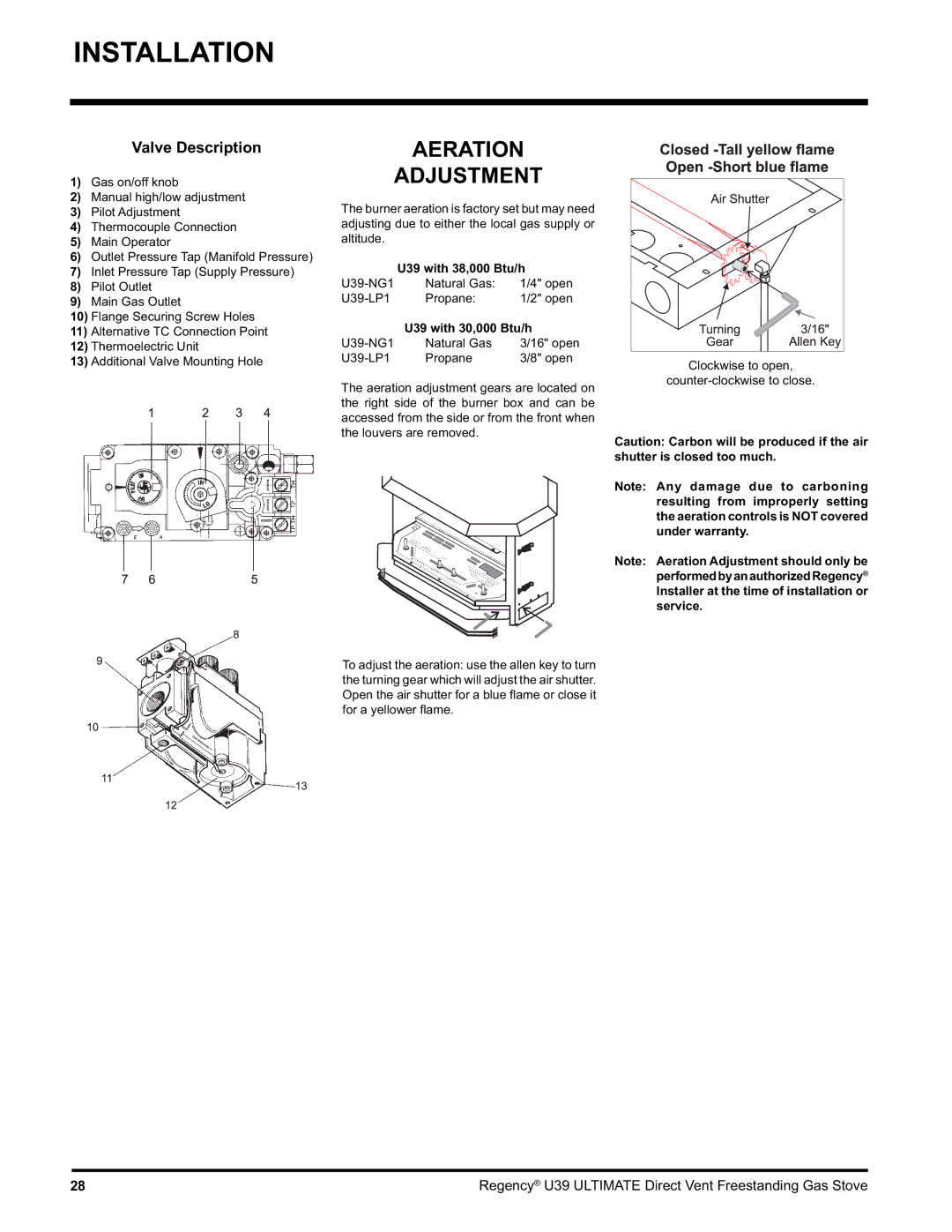
U39-LP1, U39-NG1 specifications
The Regency U39-LP1 and U39-NG1 are innovative heating appliances designed for modern homes, emphasizing both efficiency and style. These units encapsulate the essence of contemporary design while ensuring high-performance heating solutions. The U39 series stands out for its user-friendly features and advanced technologies that cater to the demands of varied environments.One of the main features of the U39-LP1 is its propane-fueled operation, allowing it to generate an impressive amount of heat while remaining energy-efficient. The unit is designed with a remarkable heating capacity, making it ideal for larger spaces or for those chilly evenings where comfort is paramount. In contrast, the U39-NG1 operates on natural gas, appealing to homeowners looking for a more sustainable option. Both models allow for quick and effective heating, ensuring a cozy atmosphere within moments.
The technology embedded in both models reflects a commitment to top-tier performance. The advanced electronic ignition system provides reliability, ensuring seamless operation. The units also incorporate a built-in thermostat, which allows for precise control over the temperature, enhancing comfort while conserving energy. Furthermore, the U39 series features a sleek ceramic glass front that not only adds an aesthetic element but also enhances efficiency by radiating heat effectively into the room.
Another hallmark of the Regency U39 series is its design versatility. Both models are available in various finishes, enabling them to blend seamlessly into different décor styles, whether traditional, modern, or minimalist. The compact dimensions of these units ensure they fit effortlessly into a variety of spaces, from living rooms to basements.
Safety is also a significant focus with the U39-LP1 and U39-NG1. The units come equipped with a variety of safety features, including automatic shut-off and heat-resistant materials, ensuring peace of mind for users.
In summary, the Regency U39-LP1 and U39-NG1 models exemplify modern heating solutions characterized by efficiency, advanced technology, and stylish design. With their user-centric features and commitment to safety, these units are perfect additions for anyone seeking warmth and comfort in their homes. Whether powered by propane or natural gas, the U39 series continues to redefine the standard for home heating.

