MAINTENANCE
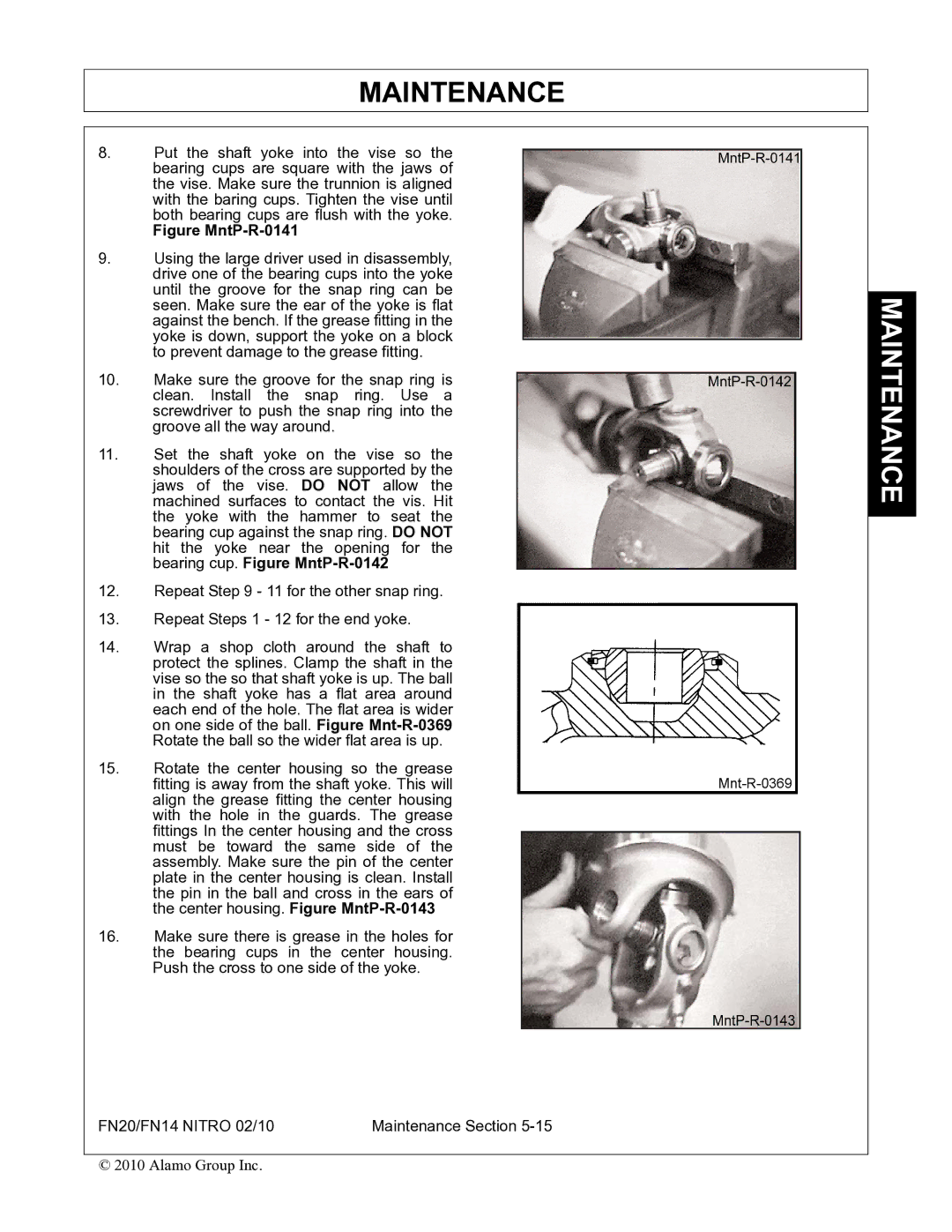
8.Put the shaft yoke into the vise so the bearing cups are square with the jaws of the vise. Make sure the trunnion is aligned with the baring cups. Tighten the vise until both bearing cups are flush with the yoke.
Figure MntP-R-0141
9.Using the large driver used in disassembly, drive one of the bearing cups into the yoke until the groove for the snap ring can be seen. Make sure the ear of the yoke is flat against the bench. If the grease fitting in the yoke is down, support the yoke on a block to prevent damage to the grease fitting.
10.Make sure the groove for the snap ring is clean. Install the snap ring. Use a screwdriver to push the snap ring into the groove all the way around.
11.Set the shaft yoke on the vise so the shoulders of the cross are supported by the jaws of the vise. DO NOT allow the machined surfaces to contact the vis. Hit the yoke with the hammer to seat the bearing cup against the snap ring. DO NOT hit the yoke near the opening for the bearing cup. Figure
12.Repeat Step 9 - 11 for the other snap ring.
13.Repeat Steps 1 - 12 for the end yoke.
14.Wrap a shop cloth around the shaft to protect the splines. Clamp the shaft in the vise so the so that shaft yoke is up. The ball in the shaft yoke has a flat area around each end of the hole. The flat area is wider on one side of the ball. Figure
15.Rotate the center housing so the grease fitting is away from the shaft yoke. This will align the grease fitting the center housing with the hole in the guards. The grease fittings In the center housing and the cross must be toward the same side of the assembly. Make sure the pin of the center plate in the center housing is clean. Install the pin in the ball and cross in the ears of the center housing. Figure
16.Make sure there is grease in the holes for the bearing cups in the center housing. Push the cross to one side of the yoke.
FN20/FN14 NITRO 02/10 | Maintenance Section |
© 2010 Alamo Group Inc.