MAINTENANCE
MAINTENANCE
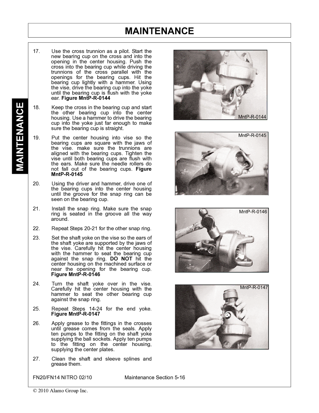
17.Use the cross trunnion as a pilot. Start the new bearing cup on the cross and into the opening in the center housing. Push the cross into the bearing cup while driving the trunnions of the cross parallel with the openings for the bearing cups. Hit the bearing cup lightly with a hammer. Using the vise, drive the bearing cup into the yoke until the bearing cup is flush with the yoke ear. Figure
18.Keep the cross in the bearing cup and start the other bearing cup into the center housing. Use a hammer to drive the bearing cup into the yoke just far enough to make sure the bearing cup is straight.
19.Put the center housing into vise so the bearing cups are square with the jaws of the vise. make sure the trunnions are aligned with the bearing cups. Tighten the vise until both bearing cups are flush with the ears. Make sure the needle rollers do not fall out of the bearing cups. Figure
MntP-R-0145
20.Using the driver and hammer, drive one of the bearing cups into the center housing until the groove for the snap ring can be seen on the bearing cup.
21.Install the snap ring. Make sure the snap ring is seated in the groove all the way around.
22.Repeat Steps
23.Set the shaft yoke on the vise so the ears of the shaft yoke are supported by the jaws of the vise. Carefully hit the center housing with the hammer to seat the bearing cup against the snap ring. DO NOT hit the center housing on the machined surface or near the opening for the bearing cup.
Figure MntP-R-0146
24.Turn the shaft yoke over in the vise. Carefully hit the center housing with the hammer to seat the other bearing cup against the snap ring.
25.Repeat Steps
Figure MntP-R-0147
26.Apply grease to the fittings in the crosses until grease comes from the seals. Apply ten pumps to the fitting on the shaft yoke supplying the ball sockets. Apply ten pumps to the fitting on the center housing, supplying the center plates.
27.Clean the shaft and sleeve splines and grease them.
FN20/FN14 NITRO 02/10 | Maintenance Section |
© 2010 Alamo Group Inc.
