OPERATION
OPERATION
Before operating the Implement, check to make sure the Implement input driveline will not
bottom out or become disengaged. Bottoming out occurs when the inner shaft penetrates the outer housing until the assembly becomes
When fitting the mower to the tractor , the telescoping driveline must be inspected to ensure that at its most compressed position, the shafts do not “bottom out”, and when at its farthest extended postion, there is sufficient engagement between the profiles to operate safely. At its shortest length, there must be at least at 1” clearance between each profile end and opposite profile universal joint. At its farthest operating extension, a minimum profile engagement of 6” must be maintained.
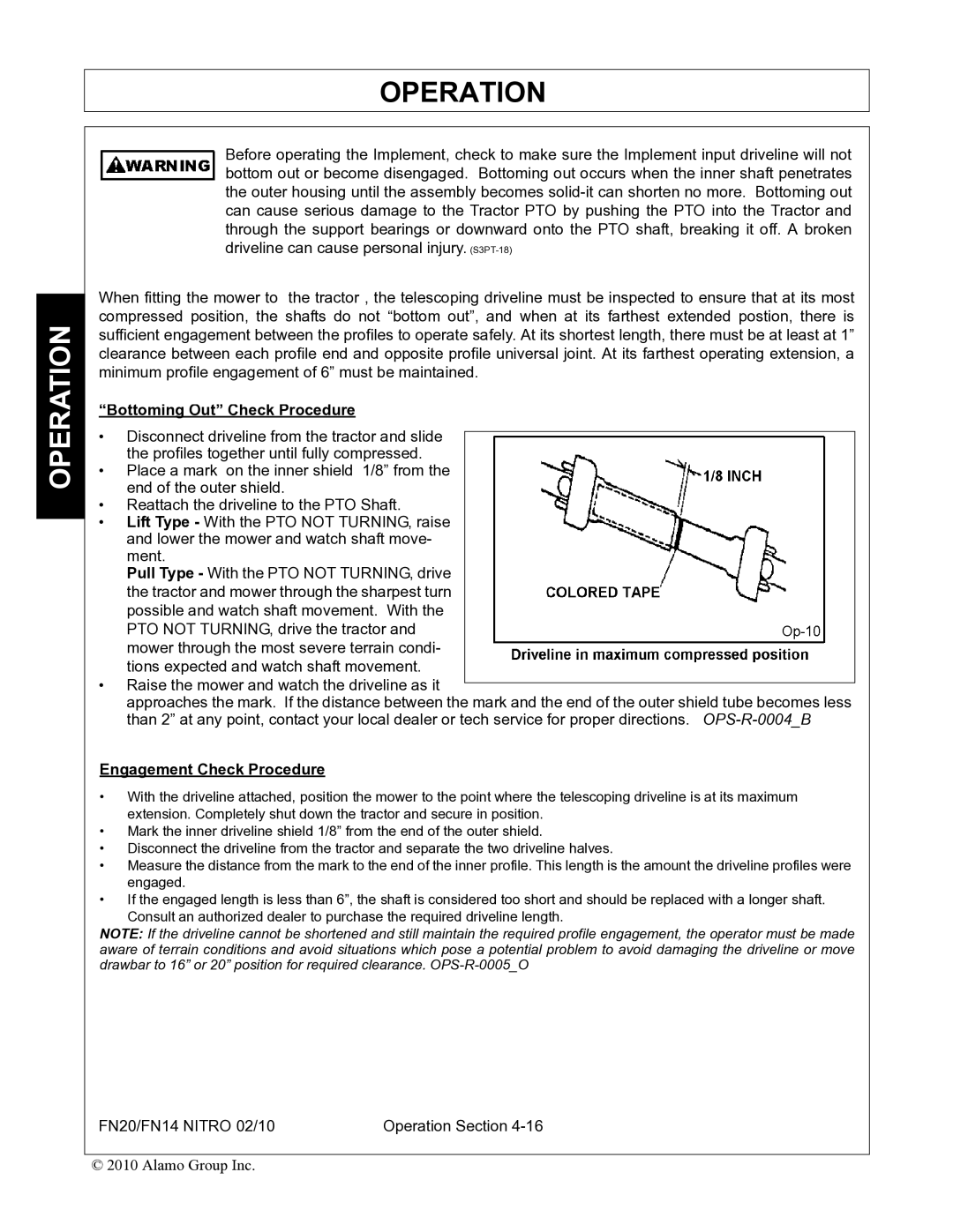
“Bottoming Out” Check Procedure
•Disconnect driveline from the tractor and slide the profiles together until fully compressed.
•Place a mark on the inner shield 1/8” from the end of the outer shield.
•Reattach the driveline to the PTO Shaft.
•Lift Type - With the PTO NOT TURNING, raise and lower the mower and watch shaft move- ment.
Pull Type - With the PTO NOT TURNING, drive the tractor and mower through the sharpest turn possible and watch shaft movement. With the PTO NOT TURNING, drive the tractor and mower through the most severe terrain condi- tions expected and watch shaft movement.
•Raise the mower and watch the driveline as it
approaches the mark. If the distance between the mark and the end of the outer shield tube becomes less than 2” at any point, contact your local dealer or tech service for proper directions.
Engagement Check Procedure
•With the driveline attached, position the mower to the point where the telescoping driveline is at its maximum extension. Completely shut down the tractor and secure in position.
•Mark the inner driveline shield 1/8” from the end of the outer shield.
•Disconnect the driveline from the tractor and separate the two driveline halves.
•Measure the distance from the mark to the end of the inner profile. This length is the amount the driveline profiles were engaged.
•If the engaged length is less than 6”, the shaft is considered too short and should be replaced with a longer shaft.
Consult an authorized dealer to purchase the required driveline length.
NOTE: If the driveline cannot be shortened and still maintain the required profile engagement, the operator must be made aware of terrain conditions and avoid situations which pose a potential problem to avoid damaging the driveline or move drawbar to 16” or 20” position for required clearance.
FN20/FN14 NITRO 02/10 | Operation Section |
© 2010 Alamo Group Inc.