ASSEMBLY
TO MOUNT THE TABLE SAW TO THE LEG STAND
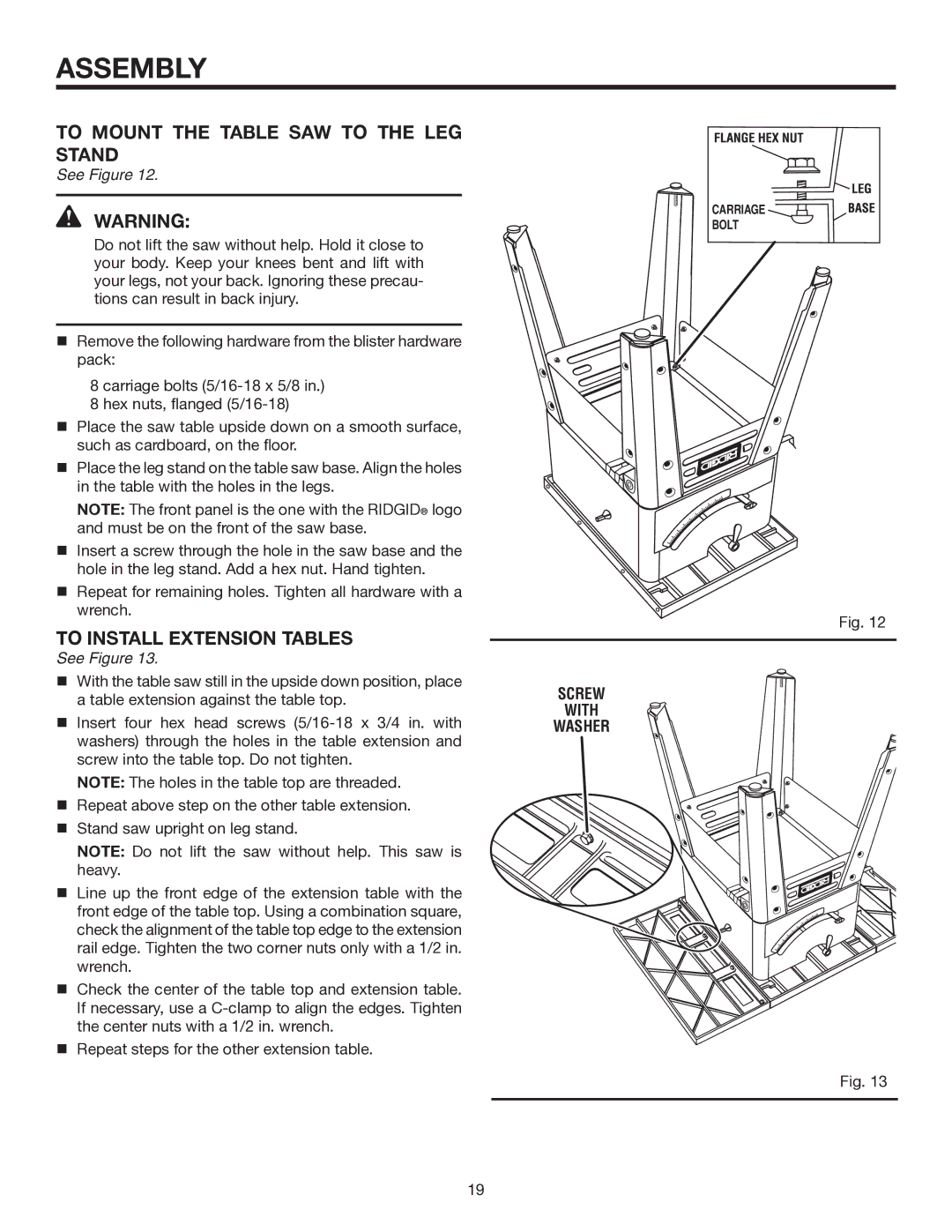
See Figure 12.
WARNING:
Do not lift the saw without help. Hold it close to your body. Keep your knees bent and lift with your legs, not your back. Ignoring these precau- tions can result in back injury.
Remove the following hardware from the blister hardware pack:
8 carriage bolts
8 hex nuts, flanged
Place the saw table upside down on a smooth surface, such as cardboard, on the floor.
Place the leg stand on the table saw base. Align the holes in the table with the holes in the legs.
NOTE: The front panel is the one with the RIDGID® logo and must be on the front of the saw base.
Insert a screw through the hole in the saw base and the hole in the leg stand. Add a hex nut. Hand tighten.
Repeat for remaining holes. Tighten all hardware with a wrench.
TO INSTALL EXTENSION TABLES
See Figure 13.
With the table saw still in the upside down position, place a table extension against the table top.
Insert four hex head screws
NOTE: The holes in the table top are threaded.
Repeat above step on the other table extension.
Stand saw upright on leg stand.
NOTE: Do not lift the saw without help. This saw is heavy.
Line up the front edge of the extension table with the front edge of the table top. Using a combination square, check the alignment of the table top edge to the extension rail edge. Tighten the two corner nuts only with a 1/2 in. wrench.
Check the center of the table top and extension table. If necessary, use a
Repeat steps for the other extension table.
CARRIAGE ![]()
![]()
BOLT
Fig. 12
SCREW
WITH
WASHER
Fig. 13
19