ASSEMBLY
TO INSTALL THE HERC-U-LIFT™ MOBILE BASE TO THE LEG STAND
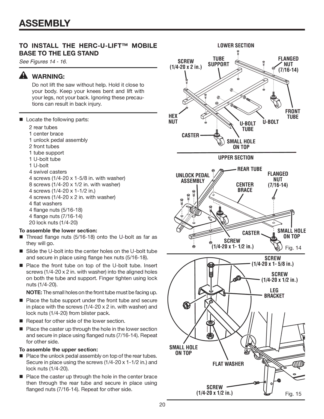
See Figures 14 - 16.
WARNING:
Do not lift the saw without help. Hold it close to your body. Keep your knees bent and lift with your legs, not your back. Ignoring these precau- tions can result in back injury.
Locate the following parts:
2 rear tubes
1 center brace
1 unlock pedal assembly
2 front tubes
1 tube support
1
1
4 swivel casters
4 screws
4 screws
4 screws
4 flat washers
4 flange nuts
4 flange nuts
20 lock nuts
To assemble the lower section:
Thread flange nuts
Slide the
Place the front tube on top of the
NOTE: The small holes on the front tube must be facing up.
Place the tube support under the front tube and secure in place with the screws
Repeat for other side of the lower section.
Place the caster up through the hole in the lower section and secure in place using flanged nuts
To assemble the upper section:
Place the unlock pedal assembly on top of the rear tubes. Secure in place using the screws
Place the caster up through the hole in the center brace then through the rear tube and secure in place using flanged nuts
| LOWER SECTION |
| |
SCREW | TUBE | FLANGED | |
SUPPORT | NUT | ||
| |||
|
|
HEX |
| FRONT |
| TUBE | |
NUT | ||
CASTER | TUBE |
|
SMALL HOLE |
| |
|
| |
| ON TOP |
|
| UPPER SECTION |
|
UNLOCK PEDAL | REAR TUBE | FLANGED |
| ||
ASSEMBLY | CENTER | NUT |
| ||
| BRACE |
|
CASTER | SMALL HOLE | |
ON TOP | ||
SCREW | ||
| ||
Fig. 14 |
SCREW
![]()
![]()
SCREW
![]()
![]()
![]()
![]()
LEG
![]() BRACKET
BRACKET
SMALL HOLE
ON TOP
FLAT WASHER |
|
SCREW |
|
Fig. 15 |
20