ASSEMBLY
Position the rip fence over the right miter gauge groove. Place the front of the rip fence on the front rail before lowering the back of the rip fence onto the back rail.
Open this Operator's Manual so that eight pages are separated from the rest. Using these pages as a guide, place them under the rip fence. The pages should slide from the front to the back of the rip fence.
If the rip fence is too high or too low, loosen the hex nuts holding the rails in place and adjust the rails up or down as needed.
Once the proper alignment is made, wrench tighten the hex nuts.
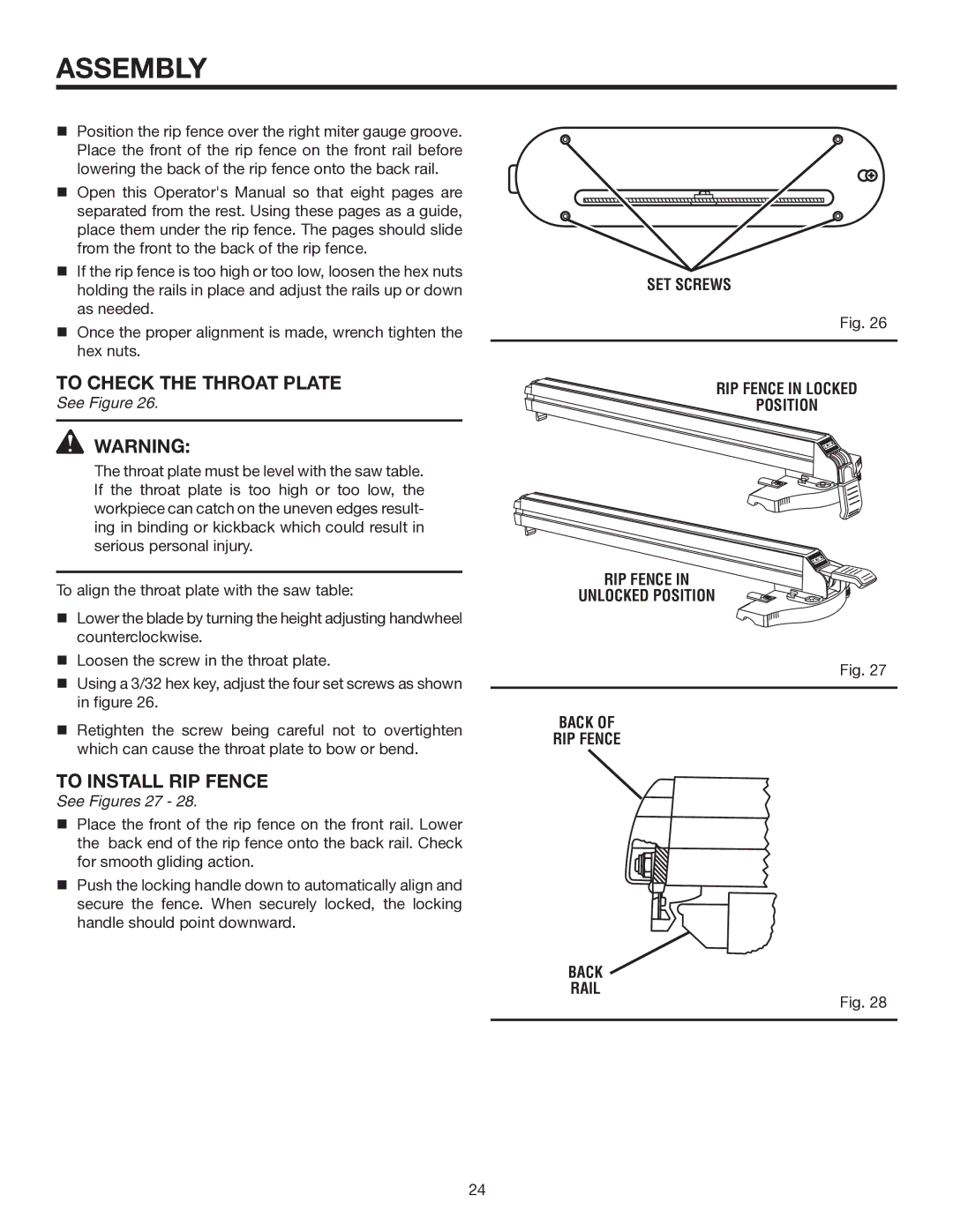
TO CHECK THE THROAT PLATE
See Figure 26.
![]() WARNING:
WARNING:
The throat plate must be level with the saw table. If the throat plate is too high or too low, the workpiece can catch on the uneven edges result- ing in binding or kickback which could result in serious personal injury.
To align the throat plate with the saw table:
SET SCREWS
Fig. 26
RIP FENCE IN LOCKED
POSITION
RIP FENCE IN
UNLOCKED POSITION
Lower the blade by turning the height adjusting handwheel counterclockwise.
Loosen the screw in the throat plate.
Using a 3/32 hex key, adjust the four set screws as shown in figure 26.
Retighten the screw being careful not to overtighten which can cause the throat plate to bow or bend.
TO INSTALL RIP FENCE
See Figures 27 - 28.
Place the front of the rip fence on the front rail. Lower the back end of the rip fence onto the back rail. Check for smooth gliding action.
Push the locking handle down to automatically align and secure the fence. When securely locked, the locking handle should point downward.
BACK OF
RIP FENCE
BACK  RAIL
RAIL
Fig. 27
Fig. 28
24