ADJUSTMENTS
Reinstall the height adjusting handwheel.
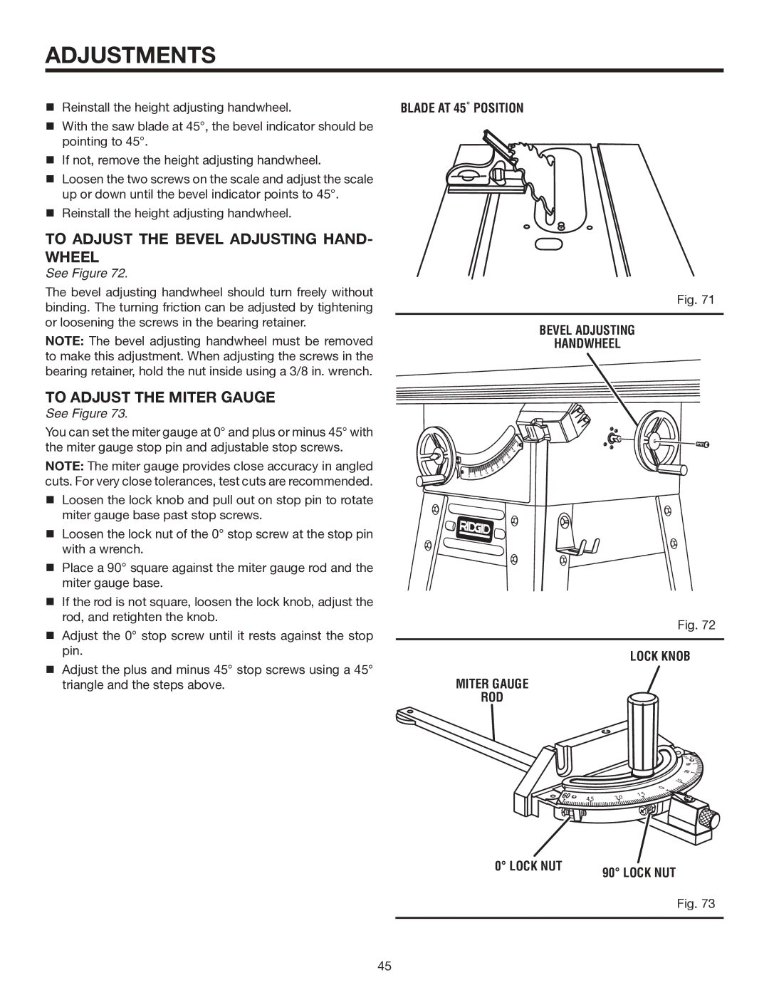
With the saw blade at 45°, the bevel indicator should be pointing to 45°.
If not, remove the height adjusting handwheel.
Loosen the two screws on the scale and adjust the scale up or down until the bevel indicator points to 45°.
Reinstall the height adjusting handwheel.
TO ADJUST THE BEVEL ADJUSTING HAND- WHEEL
See Figure 72.
The bevel adjusting handwheel should turn freely without binding. The turning friction can be adjusted by tightening or loosening the screws in the bearing retainer.
NOTE: The bevel adjusting handwheel must be removed to make this adjustment. When adjusting the screws in the bearing retainer, hold the nut inside using a 3/8 in. wrench.
TO ADJUST THE MITER GAUGE
See Figure 73.
You can set the miter gauge at 0° and plus or minus 45° with the miter gauge stop pin and adjustable stop screws.
NOTE: The miter gauge provides close accuracy in angled cuts. For very close tolerances, test cuts are recommended.
Loosen the lock knob and pull out on stop pin to rotate miter gauge base past stop screws.
Loosen the lock nut of the 0° stop screw at the stop pin with a wrench.
Place a 90° square against the miter gauge rod and the miter gauge base.
If the rod is not square, loosen the lock knob, adjust the rod, and retighten the knob.
Adjust the 0° stop screw until it rests against the stop pin.
Adjust the plus and minus 45° stop screws using a 45° triangle and the steps above.
BLADE AT 45˚ POSITION
Fig. 71
BEVEL ADJUSTING
HANDWHEEL
Fig. 72
LOCK KNOB
MITER GAUGE
ROD
0° LOCK NUT | 90° LOCK NUT |
|
Fig. 73
45
