Model Number and Options
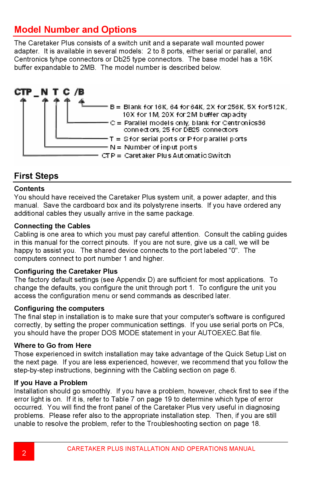
The Caretaker Plus consists of a switch unit and a separate wall mounted power adapter. It is available in several models: 2 to 8 ports, either serial or parallel, and Centronics tyhpe connectors or Db25 type connectors. The base model has a 16K buffer expandable to 2MB. The model number is described below.
First Steps
Contents
You should have received the Caretaker Plus system unit, a power adapter, and this manual. Save the cardboard box and its polystyrene inserts. If you have ordered any additional cables they usually arrive in the same package.
Connecting the Cables
Cabling is one area to which you must pay careful attention. Consult the cabling guides in this manual for the correct pinouts. If you are not sure, give us a call, we will be happy to assist you. The shared device connects to the port labeled "0". The computers connect to port number 1 and higher.
Configuring the Caretaker Plus
The factory default settings (see Appendix D) are sufficient for most applications. To change the defaults, you configure the unit through port 1. To configure the unit you access the configuration menu or send commands as described later.
Configuring the computers
The final step in installation is to make sure that your computer's software is configured correctly, by setting the proper communication settings. If you use serial ports on PCs, you should have the proper DOS MODE statement in your AUTOEXEC.Bat file.
Where to Go from Here
Those experienced in switch installation may take advantage of the Quick Setup List on the next page. If you are less experienced, however, we recommend that you follow the
If you Have a Problem
Installation should go smoothly. If you have a problem, however, check first to see if the error light is on. If it is, refer to Table 7 on page 19 to determine which type of error occurred. You will find the front panel of the Caretaker Plus very useful in diagnosing problems. Please refer also to the appropriate installation step. Then, if you are still unable to resolve the problem, refer to the Troubleshooting section on page 18.
2
CARETAKER PLUS INSTALLATION AND OPERATIONS MANUAL