Long Test with Loopback
This test is entered by pressing the advance switch only while powering up the unit with the on/off switch. Special loopback connectors should be connected to each Caretaker Plus port.
Tests
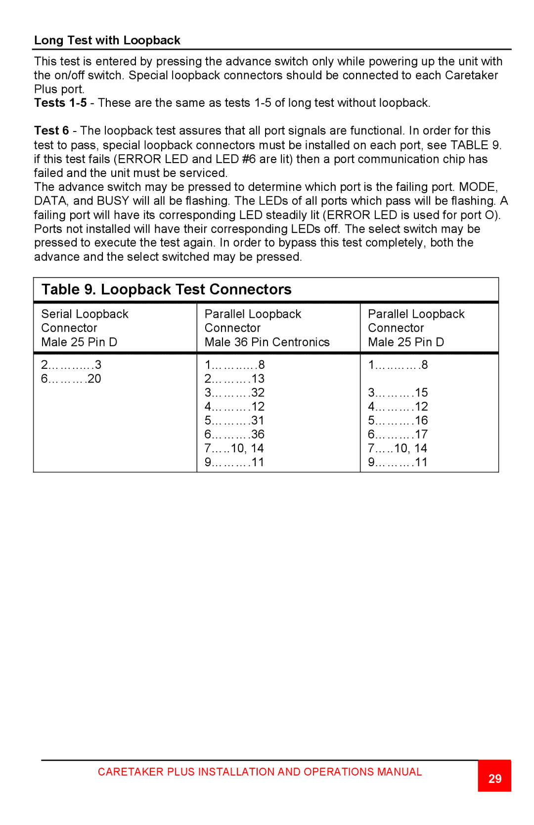
Test 6 - The loopback test assures that all port signals are functional. In order for this test to pass, special loopback connectors must be installed on each port, see TABLE 9. if this test fails (ERROR LED and LED #6 are lit) then a port communication chip has failed and the unit must be serviced.
The advance switch may be pressed to determine which port is the failing port. MODE, DATA, and BUSY will all be flashing. The LEDs of all ports which pass will be flashing. A failing port will have its corresponding LED steadily lit (ERROR LED is used for port O). Ports not installed will have their corresponding LEDs off. The select switch may be pressed to execute the test again. In order to bypass this test completely, both the advance and the select switched may be pressed.
Table 9. Loopback Test Connectors
Serial Loopback |
| Parallel Loopback |
| Parallel Loopback |
Connector |
| Connector |
| Connector |
Male 25 Pin D |
| Male 36 Pin Centronics |
| Male 25 Pin D |
|
|
|
|
|
2……..….3 |
| 1……..….8 |
| 1…..…….8 |
|
| |||
6……….20 |
| 2……….13 |
|
|
|
| 3……….32 |
| 3……….15 |
|
| 4……….12 |
| 4……….12 |
|
| 5……….31 |
| 5……….16 |
|
| 6……….36 |
| 6……….17 |
|
| 7…..10, 14 |
| 7…..10, 14 |
|
| 9……….11 |
| 9……….11 |
|
|
|
|
|
CARETAKER PLUS INSTALLATION AND OPERATIONS MANUAL
29