Appendix C: MP1000 Memory Board
This memory board provides optional,
About the Board
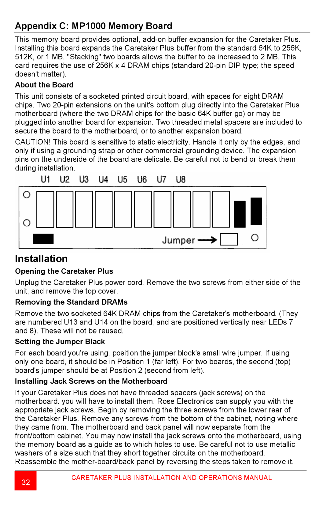
This unit consists of a socketed printed circuit board, with spaces for eight DRAM chips. Two
CAUTION! This board is sensitive to static electricity. Handle it only by the edges, and only if using a grounding strap or other commercial grounding device. The expansion pins on the underside of the board are delicate. Be careful not to bend or break them during installation.
Installation
Opening the Caretaker Plus
Unplug the Caretaker Plus power cord. Remove the two screws from either side of the unit, and remove the top cover.
Removing the Standard DRAMs
Remove the two socketed 64K DRAM chips from the Caretaker's motherboard. (They are numbered U13 and U14 on the board, and are positioned vertically near LEDs 7 and 8). These will not be reused.
Setting the Jumper Black
For each board you're using, position the jumper block's small wire jumper. If using only one board, it should be in Position 1 (far left). For two boards, the second (top) board's jumper should be at Position 2 (second from left).
Installing Jack Screws on the Motherboard
If your Caretaker Plus does not have threaded spacers (jack screws) on the motherboard. you will have to install them. Rose Electronics can supply you with the appropriate jack screws. Begin by removing the three screws from the lower rear of the Caretaker Plus. Remove any screws from the bottom of the cabinet, noting where they came from. The motherboard and back panel will now separate from the front/bottom cabinet. You may now install the jack screws onto the motherboard, using the memory board as a guide as to which holes to use. Be careful not to use metallic washers of a size such that they short together circuits on the motherboard. Reassemble the
32