Viewing the Connection Panel
![]() Connecting an Aerial or Cable Television Network (depending on the model)
Connecting an Aerial or Cable Television Network (depending on the model)
To view television channels correctly, a signal must be received by the set from one of the following sources:
-An outdoor aerial
-A cable television network
-A satellite network
 Connecting a
 Set-Top Box, VCR or DVD
-Connect the RCA cable to “L - AUDIO - R” on the rear of your set and the other end to “Audio Out” connector on the DVD, VCR or DTV
-The Y, PB and PR connectors on your component device (DVD) are sometimes labeled Y,
-Connect RCA Cable to “Y”, “PB” and “PR” on the rear of your set and the other end to “Component Out” connetor of the DVD, VCR, DTV
Connect RCA audio cables to
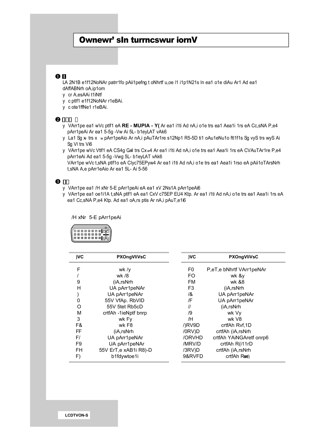
 Connecting a Computer
-Connect the 24 Pin DVI connector to the PC video connector.
-Connect the stereo audio cable to the “PC AUDIO IN” jack on the rear of your set and the other end to the “Audio Out” jack of the sound card on your computer.
➣ 24 Pin DVI connector
Pin | Description |
1 | Rx 2- |
2 | Rx 2+ |
3Grounding
4No connection
5No connection
6DDC Clock (SCL)
7DDC Data (SDA)
8Analog Vertical Sync
9 | Rx 1- |
10Rx 1+
11Grounding
12No connection
13No connection
14DDC Input Power (+5V)
15
PinDescription
16Output Signal Connection
17Rx 0-
18Rx 0+
19Grounding
20No connection
21No connection
22Grounding
23Rx C-
24Rx C+
25(C3) | Analog (Blue) |
26(C5) | Analog Grounding |
27(C4) | Analog Horizontal sync. |
28(C2) | Analog (Green) |
29(C5) | Analog Grounding |
30(C1) | Analog (Red) |
|
|