4. REFRIGERANT FLOW DIAGRAM
4-1. Refrigerant Flow Diagram
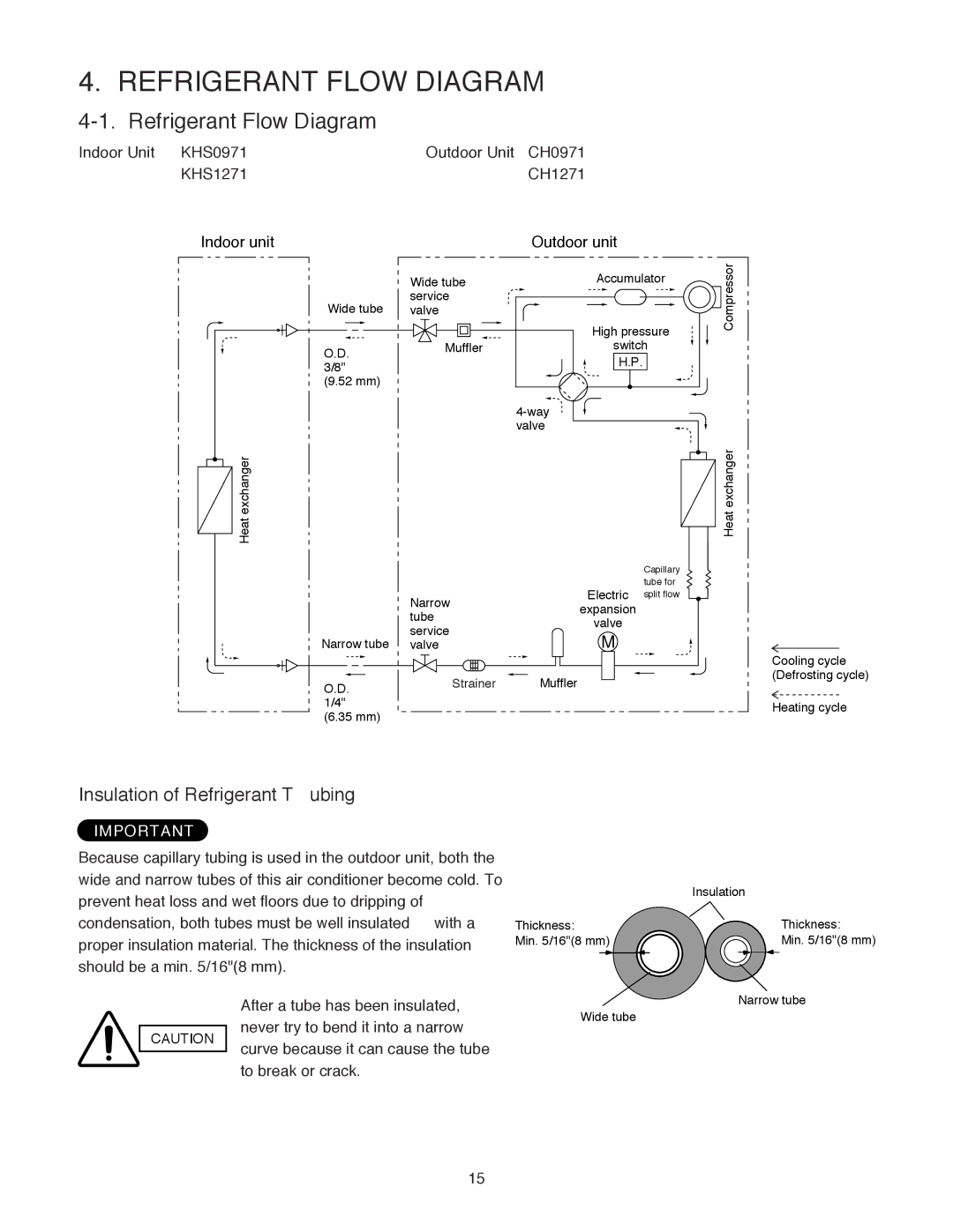
Indoor Unit KHS0971 | Outdoor Unit CH0971 |
KHS1271 | CH1271 |
Indoor unit | Outdoor unit |
| Wide tube | Accumulator | Compressor | |
Wide tube | service |
|
| |
valve |
|
| ||
|
| High pressure | ||
O.D. | Muffler | switch |
| |
| H.P. |
|
| |
3/8" |
|
|
| |
(9.52 mm) |
|
|
|
|
|
|
|
| |
|
| valve |
|
|
Heat exchanger |
|
|
| Heat exchanger |
|
|
| Capillary |
|
|
| Electric | tube for |
|
| Narrow | split flow |
| |
| expansion |
|
| |
| tube |
|
| |
| valve |
|
| |
| service |
|
| |
Narrow tube | M |
|
| |
valve |
|
| ||
O.D. | Strainer | Muffler |
|
|
1/4" |
|
|
|
|
(6.35 mm) |
|
|
|
|
Cooling cycle (Defrosting cycle)
Heating cycle
Insulation of Refrigerant Tubing
IMPORTANT
Because capillary tubing is used in the outdoor unit, both the wide and narrow tubes of this air conditioner become cold. To prevent heat loss and wet floors due to dripping of condensation, both tubes must be well insulated with a proper insulation material. The thickness of the insulation should be a min. 5/16"(8 mm).
Thickness:
Min. 5/16"(8 mm)
Insulation
Thickness:
Min. 5/16"(8 mm)
After a tube has been insulated,
CAUTION never try to bend it into a narrowWide tube curve because it can cause the tube
to break or crack.
Narrow tube
15