WARNING Loose wiring may cause the terminal to overheat or result in unit malfunction. A fire hazard may also exist. Therefore, be sure all wiring is tightly connected.
When connecting each power wire to the corresponding terminal, follow the instructions “How to connect wiring to the terminal” and fasten the wire securely tight with the fixing screw of the terminal plate.
How to connect wiring to the terminal
a) For Indoor Unit
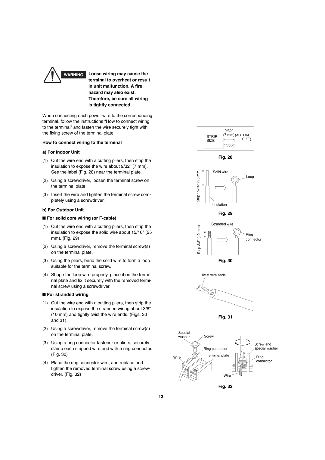
(1)Cut the wire end with a cutting pliers, then strip the insulation to expose the wire about 9/32" (7 mm). See the label (Fig. 28) near the terminal plate.
(2)Using a screwdriver, loosen the terminal screw on the terminal plate.
(3)Insert the wire and tighten the terminal screw com- pletely using a screwdriver.
b) For Outdoor Unit
■For solid core wiring (or F-cable)
(1)Cut the wire end with a cutting pliers, then strip the insulation to expose the solid wire about 15/16" (25 mm). (Fig. 29)
(2)Using a screwdriver, remove the terminal screw(s) on the terminal plate.
(3)Using the pliers, bend the solid wire to form a loop suitable for the terminal screw.
(4)Shape the loop wire properly, place it on the termi- nal plate and fix it securely with the removed termi- nal screw using a screwdriver.
■For stranded wiring
(1) | Cut the wire end with a cutting pliers, then strip the |
| insulation to expose the stranded wiring about 3/8" |
| (10 mm) and tightly twist the wire ends. (Figs. 30 |
| and 31) |
(2) | Using a screwdriver, remove the terminal screw(s) |
9/32"
STRIP | (7 mm) (ACTUAL | |
SIZE) | ||
SIZE | ||
|
Fig. 28
mm) | Solid wire | |
| ||
Strip 15/16" (25 | Loop | |
Insulation | ||
| ||
| Fig. 29 | |
mm) | Stranded wire | |
Ring | ||
(10 | ||
connector | ||
Strip 3/8" | ||
|
Fig. 30
Twist wire ends
Fig. 31
on the terminal plate. |
(3) Using a ring connector fastener or pliers, securely |
clamp each stripped wire end with a ring connector. |
Special
washer Screw
Ring connector
Screw and special washer
(Fig. 30) |
(4) Place the ring connector wire, and replace and |
tighten the removed terminal screw using a screw- |
driver. (Fig. 32) |
Wire
Terminal plate
Wire
Fig. 32
Ring connector
12