(3) Serial Communication Error Identification Procedure
If the lamps on the main body show the following conditions after the completion of
In such a case, identify the breakdown section by using the following procedure.
NOTE Refer to "Method of
Lamp
Condition
E01
E12
Quiet
(3)
Timer Operation
(2)(1)
: Off
 : Blinking
 : Illuminated
< Before the Operation >
WARNING
CAUTION
For terminal strip short circuit work or
Release the terminal strip short circuit after the completion of
Do not perform the
< Convenient Tool for | Cable | Alligator Clip | |
Alligator Clip | |||
|
< Check Items before Troubleshooting Serial Communication Start >
After confirming that the following errors do not exist, start the "Troubleshooting Serial Communication" in "Condition: E01 and E12".
1. | Mis | 6. | Reactor failure (defective insulation, etc.) |
2. | AC power failure | 7. | |
3. | Blown fuse | 8. | Overload Relay failure |
4. | Power Relay failure | 9. | Magnetic Coil failure (defective insulation, |
5. | Outdoor Fan Motor failure (defective insulation, etc.) | 10. Compressor failure (defective insulation, etc.) | |
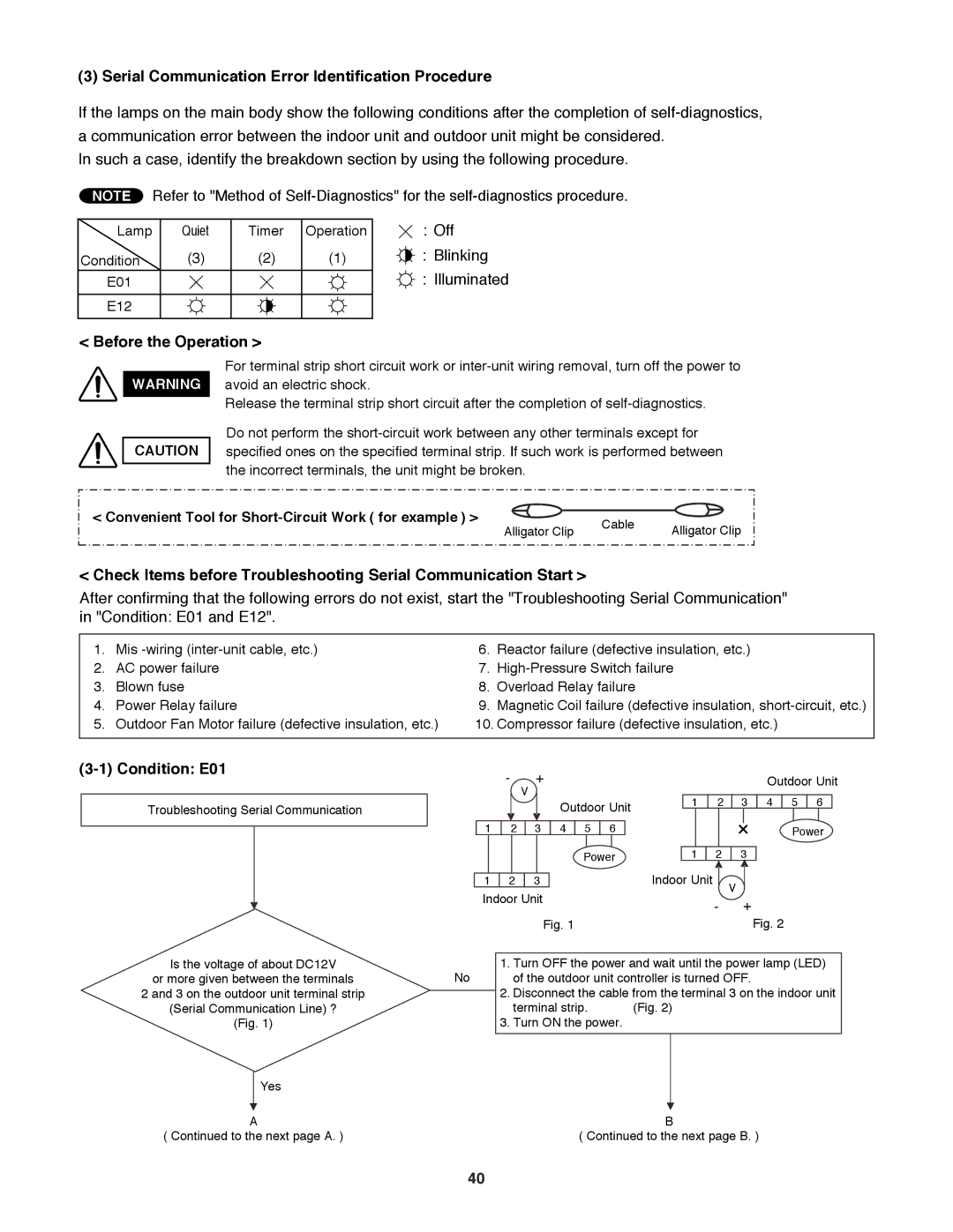
(3-1) Condition: E01
Troubleshooting Serial Communication
|
| - | + |
|
|
|
|
|
|
|
|
|
|
|
| Outdoor Unit | |||||
|
|
| V |
|
|
|
|
|
|
|
|
|
|
|
|
|
|
|
|
| |
|
|
|
|
|
| Outdoor Unit |
| 1 |
| 2 |
| 3 | 4 | 5 | 6 |
| |||||
|
|
|
|
|
|
|
|
|
|
|
|
|
|
|
| ||||||
|
|
|
|
|
|
|
|
|
|
|
|
|
|
|
|
|
|
|
|
|
|
| 1 | 2 |
| 3 |
| 4 |
| 5 |
| 6 |
|
|
|
|
|
|
|
| Power | ||
|
|
|
|
|
|
|
|
|
|
|
|
|
|
|
|
|
|
|
|
|
|
|
|
|
|
|
|
| Power |
| 1 |
| 2 |
| 3 |
|
|
|
| ||||
|
|
|
|
|
|
|
|
|
|
|
| Indoor Unit |
|
|
|
|
|
|
| ||
| 1 | 2 |
| 3 |
|
|
|
|
|
|
|
| V | ||||||||
| Indoor Unit |
|
|
|
|
|
|
|
|
|
|
| |||||||||
|
|
|
|
|
|
|
|
|
|
| - | + |
|
|
|
| |||||
|
|
|
|
|
|
|
|
|
|
|
|
|
|
|
|
|
|
| |||
|
|
|
|
| Fig. 1 |
|
|
|
|
|
|
|
|
|
| Fig. 2 | |||||
Is the voltage of about DC12V
or more given between the terminalsNo
2 and 3 on the outdoor unit terminal strip
(Serial Communication Line) ?
(Fig. 1)
Yes
A
( Continued to the next page A. )
1.Turn OFF the power and wait until the power lamp (LED) of the outdoor unit controller is turned OFF.
2.Disconnect the cable from the terminal 3 on the indoor unit
terminal strip. (Fig. 2)
3.Turn ON the power.
B
( Continued to the next page B. )
40