Installation
Connecting to a Computer
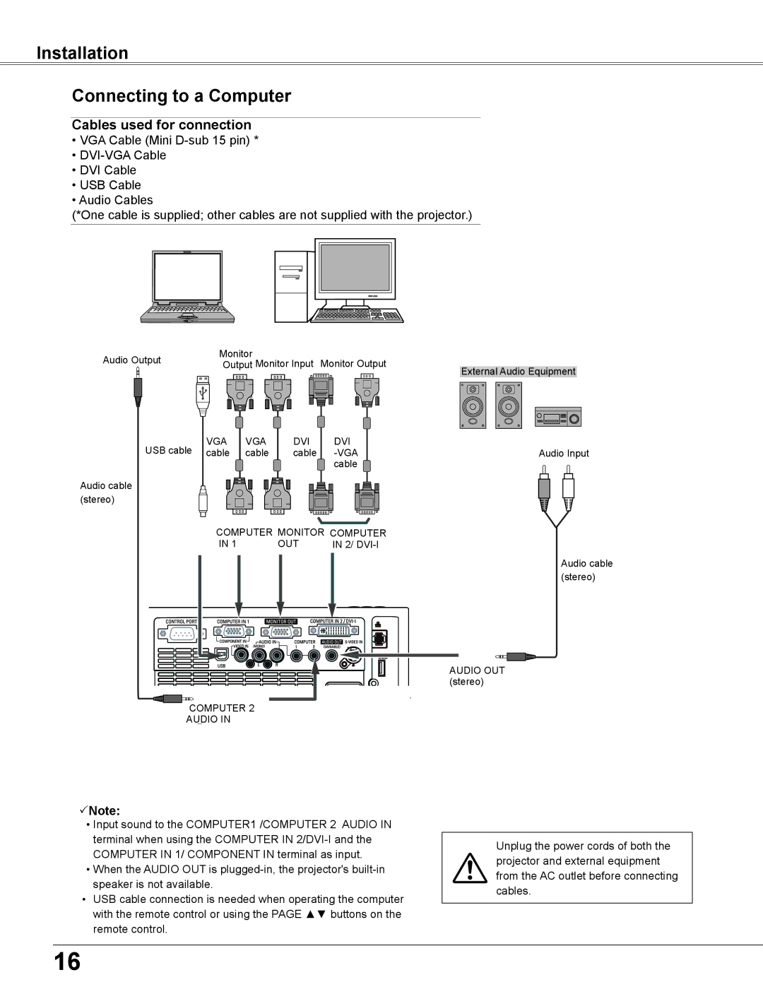
Cables used for connection
•VGA Cable (Mini
•
•DVI Cable
•USB Cable
•Audio Cables
(*One cable is supplied; other cables are not supplied with the projector.)
Audio Output |
|
| Monitor | Monitor Input Monitor Output |
| |||||||||||||||||||||
|
| Output |
| |||||||||||||||||||||||
|
|
|
| External Audio Equipment | ||||||||||||||||||||||
|
|
|
|
|
|
|
|
|
|
|
|
|
|
|
|
|
|
|
|
|
|
|
|
|
|
|
|
|
|
|
|
|
|
|
|
|
|
|
|
|
|
|
|
|
|
|
|
|
|
|
|
|
|
|
|
|
|
|
|
|
|
|
|
|
|
|
|
|
|
|
|
|
|
|
|
|
|
|
|
|
|
|
|
|
|
|
|
|
|
|
|
|
|
|
|
|
|
|
|
|
|
|
|
|
|
|
|
|
|
|
|
|
|
|
|
|
|
|
|
|
|
|
|
|
|
|
|
|
|
|
|
|
|
|
|
|
|
|
|
|
|
|
|
|
|
|
|
|
|
|
|
|
|
|
|
|
|
|
|
|
|
|
|
|
|
|
|
|
|
|
|
|
|
|
|
|
|
|
|
|
|
|
|
|
|
|
|
|
USB cable | VGA |
cable | |
Audio cable |
|
(stereo) |
|
VGA cable
DVI cable
DVI |
|
Audio Input | |
cable |
|
COMPUTER MONITOR COMPUTER
IN 1 | OUT | IN 2/ |
Audio cable (stereo)
AUDIO OUT (stereo)
![]()
![]()
![]()
![]()
![]()
![]()
![]() COMPUTER
COMPUTER![]() 2
2![]()
![]()
![]()
![]()
![]()
![]()
![]()
![]()
![]()
![]()
![]()
![]()
AUDIO IN
Note:
•Input sound to the COMPUTER1 /COMPUTER 2 AUDIO IN terminal when using the COMPUTER IN
•When the AUDIO OUT is
•USB cable connection is needed when operating the computer with the remote control or using the PAGE ▲▼ buttons on the remote control.
Unplug the power cords of both the projector and external equipment from the AC outlet before connecting cables.
16