Maintenance and Cleaning
WARNING indicator
The WARNING indicator shows the state of the function which protects the projector. Check the state of the WARNING indicator and the POWER indicator to take proper maintenance.
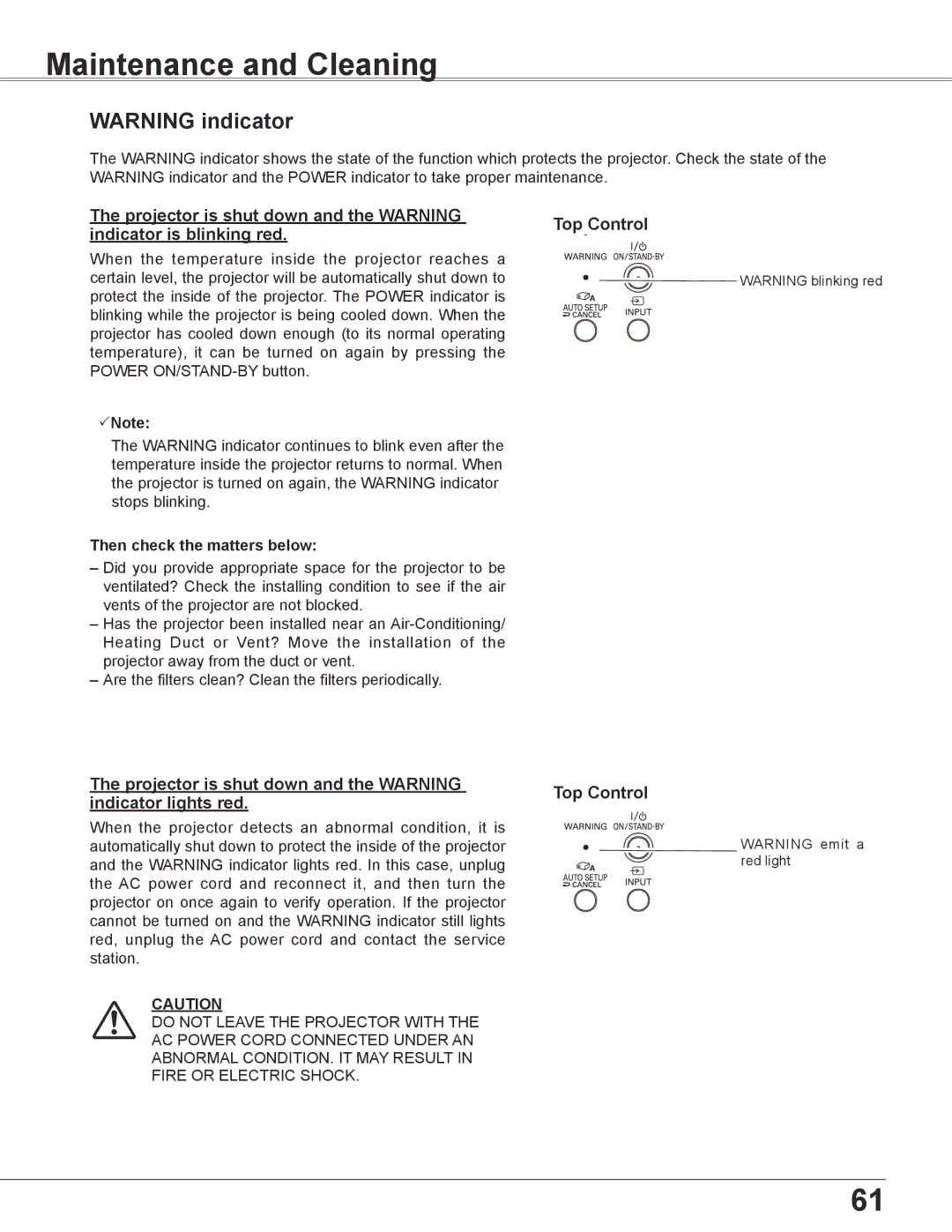
The projector is shut down and the WARNING | Top Control | |||
indicator is blinking red. | ||||
|
|
| ||
When the temperature inside the projector reaches a |
|
|
| |
|
|
| ||
|
|
| ||
certain level, the projector will be automatically shut down to |
|
| WARNING blinking red | |
protect the inside of the projector. The POWER indicator is |
|
|
| |
blinking while the projector is being cooled down. When the |
|
|
| |
|
|
| ||
|
|
| ||
projector has cooled down enough (to its normal operating |
|
|
| |
temperature), it can be turned on again by pressing the |
|
|
| |
POWER |
|
|
| |
Note: |
|
|
| |
The WARNING indicator continues to blink even after the temperature inside the projector returns to normal. When the projector is turned on again, the WARNING indicator stops blinking.
Then check the matters below:
–Did you provide appropriate space for the projector to be ventilated? Check the installing condition to see if the air vents of the projector are not blocked.
–Has the projector been installed near an
–Are the filters clean? Clean the filters periodically.
The projector is shut down and the WARNING | Top Control | |
indicator lights red. | ||
|
When the projector detects an abnormal condition, it is automatically shut down to protect the inside of the projector and the WARNING indicator lights red. In this case, unplug the AC power cord and reconnect it, and then turn the projector on once again to verify operation. If the projector cannot be turned on and the WARNING indicator still lights red, unplug the AC power cord and contact the service station.
CAUTION
DO NOT LEAVE THE PROJECTOR WITH THE
AC POWER CORD CONNECTED UNDER AN
ABNORMAL CONDITION. IT MAY RESULT IN
FIRE OR ELECTRIC SHOCK.
WARNING emit a red light
61