Setting
Lamp control
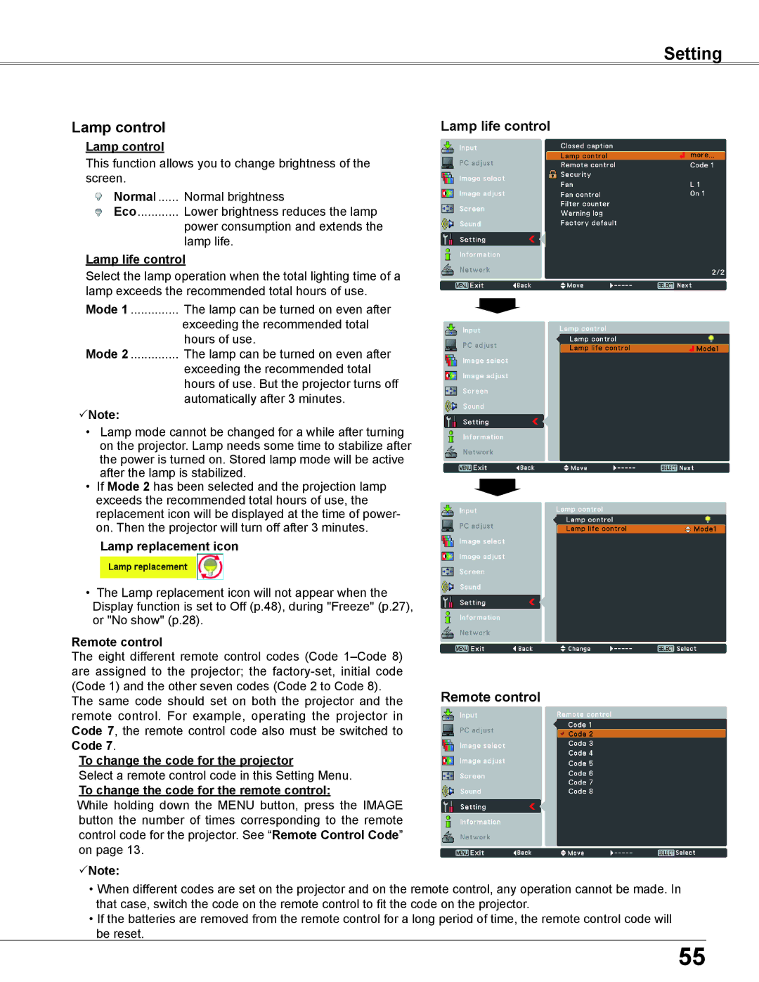
Lamp control
This function allows you to change brightness of the screen.
Normal | Normal brightness |
Eco | Lower brightness reduces the lamp |
| power consumption and extends the |
| lamp life. |
Lamp life control
Select the lamp operation when the total lighting time of a lamp exceeds the recommended total hours of use.
Mode 1 | The lamp can be turned on even after |
| exceeding the recommended total |
Mode 2 | hours of use. |
The lamp can be turned on even after | |
| exceeding the recommended total |
| hours of use. But the projector turns off |
Note: | automatically after 3 minutes. |
|
•Lamp mode cannot be changed for a while after turning on the projector. Lamp needs some time to stabilize after the power is turned on. Stored lamp mode will be active after the lamp is stabilized.
•If Mode 2 has been selected and the projection lamp exceeds the recommended total hours of use, the replacement icon will be displayed at the time of power- on. Then the projector will turn off after 3 minutes.
Lamp replacement icon
•The Lamp replacement icon will not appear when the Display function is set to Off (p.48), during "Freeze" (p.27), or "No show" (p.28).
Remote control
The eight different remote control codes (Code
The same code should set on both the projector and the remote control. For example, operating the projector in Code 7, the remote control code also must be switched to Code 7.
To change the code for the projector
Select a remote control code in this Setting Menu.
To change the code for the remote control:
While holding down the MENU button, press the IMAGE button the number of times corresponding to the remote control code for the projector. See “Remote Control Code” on page 13.
Note:
Lamp life control
Remote control
•When different codes are set on the projector and on the remote control, any operation cannot be made. In that case, switch the code on the remote control to fit the code on the projector.
•If the batteries are removed from the remote control for a long period of time, the remote control code will be reset.
55