Micrologic™ 2.0A, 3.0A, 5.0A, and 6.0A Electronic Trip Units | |
Section | Rev. 01, 07/2012 |
|
|
ENGLISH
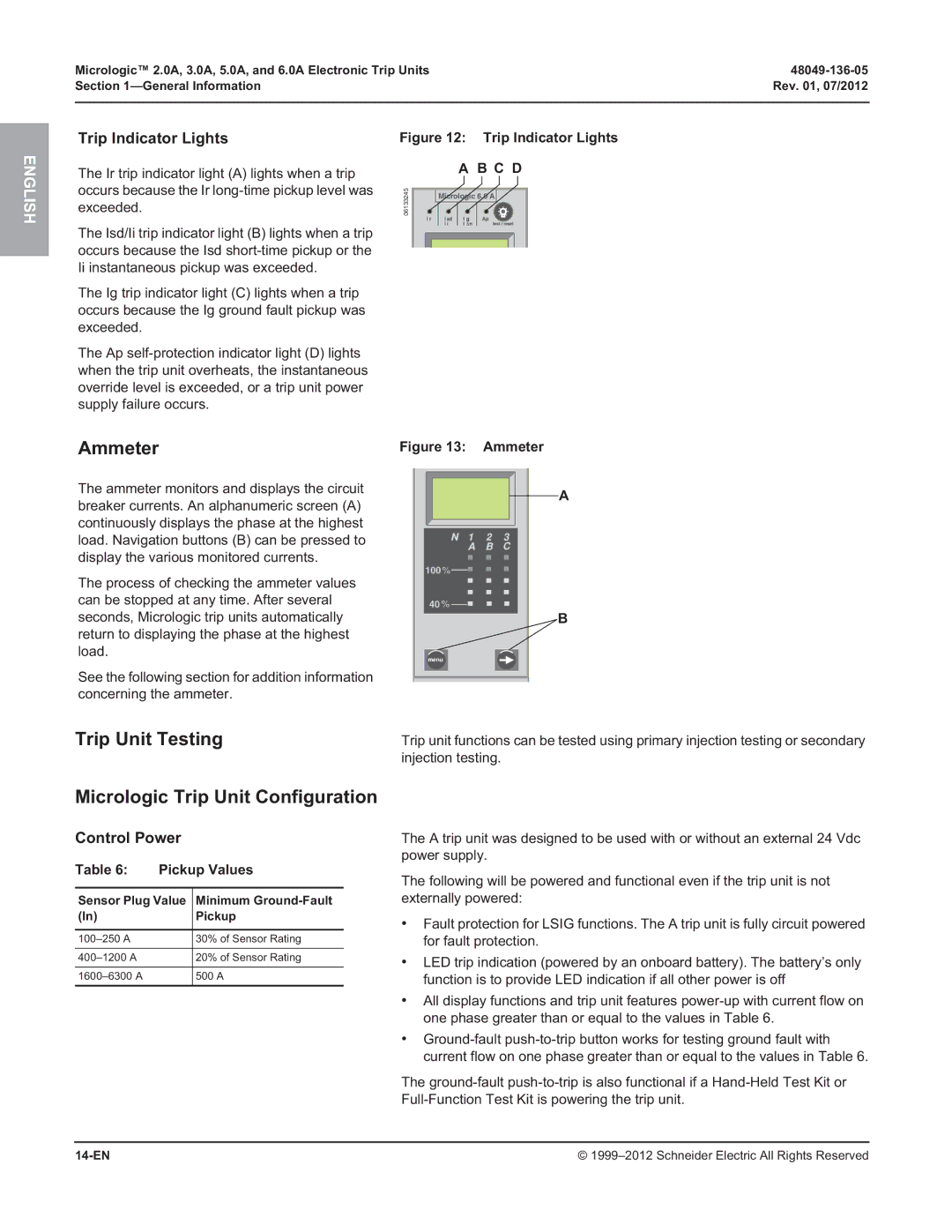
Trip Indicator Lights
The Ir trip indicator light (A) lights when a trip occurs because the Ir
The Isd/Ii trip indicator light (B) lights when a trip occurs because the Isd
The Ig trip indicator light (C) lights when a trip occurs because the Ig ground fault pickup was exceeded.
The Ap
Figure 12: Trip Indicator Lights
A B C D
06133245 | 6.0 A |
|
Ammeter
The ammeter monitors and displays the circuit breaker currents. An alphanumeric screen (A) continuously displays the phase at the highest load. Navigation buttons (B) can be pressed to display the various monitored currents.
The process of checking the ammeter values can be stopped at any time. After several seconds, Micrologic trip units automatically return to displaying the phase at the highest load.
See the following section for addition information concerning the ammeter.
Figure 13: | Ammeter |
| A |
100 % |
|
40 % | B |
| |
menu |
|
Trip Unit Testing | Trip unit functions can be tested using primary injection testing or secondary |
| injection testing. |
Micrologic Trip Unit Configuration |
|
Control Power
Table 6: Pickup Values
Sensor Plug Value Minimum
(In) | Pickup |
30% of Sensor Rating | |
20% of Sensor Rating | |
500 A |
The A trip unit was designed to be used with or without an external 24 Vdc power supply.
The following will be powered and functional even if the trip unit is not externally powered:
•Fault protection for LSIG functions. The A trip unit is fully circuit powered for fault protection.
•LED trip indication (powered by an onboard battery). The battery’s only function is to provide LED indication if all other power is off
•All display functions and trip unit features
•
The
© |