Micrologic™ 2.0A, 3.0A, 5.0A, and 6.0A Electronic Trip Units | |
Section | Rev. 01, 07/2012 |
|
|
Section 2—Ammeter
ENGLISH
Display
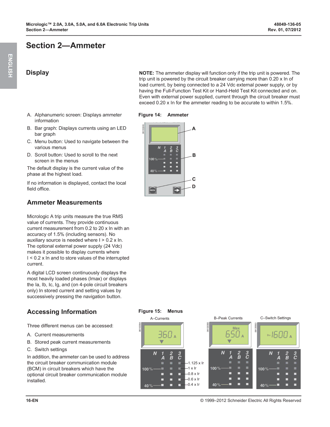
A.Alphanumeric screen: Displays ammeter information
B.Bar graph: Displays currents using an LED bar graph
C.Menu button: Used to navigate between the various menus
D.Scroll button: Used to scroll to the next screen in the menus
The default display is the current value of the phase at the highest load.
If no information is displayed, contact the local field office.
NOTE: The ammeter display will function only if the trip unit is powered. The trip unit is powered by the circuit breaker carrying more than 0.20 x In of load current, by being connected to a 24 Vdc external power supply, or by having the
Figure 14: | Ammeter |
06133245 | A |
| |
100 % | B |
| |
40 % |
|
| C |
menu | D |
|
Ammeter Measurements
Micrologic A trip units measure the true RMS value of currents. They provide continuous current measurement from 0.2 to 20 x In with an accuracy of 1.5% (including sensors). No auxiliary source is needed where I > 0.2 x In. The optional external power supply (24 Vdc) makes it possible to display currents where
I < 0.2 x In and to store values of the interrupted current.
A digital LCD screen continuously displays the most heavily loaded phases (Imax) or displays the Ia, Ib, Ic, Ig, and (on
Accessing Information
Three different menus can be accessed:
A.Current measurements
B.Stored peak current measurements
C.Switch settings
In addition, the ammeter can be used to address the circuit breaker communication module (BCM) in circuit breakers which have the optional circuit breaker communication module installed.
Figure 15: Menus
|
|
|
|
|
|
| ||||||||||||||||
06133354 |
|
|
|
|
|
|
|
|
|
|
| 06133355 |
|
|
|
|
|
|
|
|
| |
|
|
|
|
|
|
|
| Max |
| |||||||||||||
|
|
|
|
|
|
|
|
|
|
|
|
|
|
|
|
|
|
| ||||
|
|
|
|
|
| A |
|
|
|
|
|
|
|
|
|
|
| A |
| |||
|
|
|
|
|
|
|
|
|
|
|
| 1.125 x Ir |
|
|
|
|
|
|
|
|
|
|
|
|
|
|
|
|
|
|
|
|
|
|
|
|
|
|
|
|
|
|
|
| |
|
|
|
|
|
|
|
|
|
|
|
|
|
|
|
|
|
|
|
|
|
| |
|
|
|
|
|
|
|
|
|
|
|
|
|
|
|
|
|
|
|
|
|
| |
| 100 % |
|
|
|
|
|
|
|
| 1 x Ir |
| 100 % |
|
|
|
|
|
|
| |||
|
|
|
|
|
|
|
|
|
|
|
|
|
|
|
| |||||||
|
|
|
|
|
|
|
|
|
|
| 0.8 x Ir |
|
|
|
|
|
|
|
|
|
| |
|
|
|
|
|
|
|
|
|
|
|
|
|
|
|
|
|
|
|
|
| ||
|
|
|
|
|
|
|
|
|
| 0.6 x Ir |
|
|
|
|
|
|
|
|
|
| ||
|
|
|
|
|
|
|
|
|
|
|
|
|
|
|
|
|
|
|
| |||
| 40 % |
|
|
|
|
|
|
|
| 0.4 x Ir |
| 40 % |
|
|
|
|
|
|
| |||
|
|
|
|
|
|
|
|
|
|
|
|
|
|
|
|
| ||||||
|
|
|
|
|
|
|
|
|
|
|
|
|
|
|
|
|
|
|
|
|
|
|
06133353 |
|
Ir= | A |
|
100 % ![]()
![]()
40 % ![]()
![]()
| © |